– MAP/WX ranges are: 5, 10, 25, 50,
100, 200, 300*
* Two additional ranges are available in
MAP/WX, 500 and 1000, when the
radar mode is selected to FP.
• Designator Symbol is an unfilled rect-
angle with a dashed line connecting the
box to the origination of the designator.
The designator is controlled by the cen-
ter pedestal mounted joystick and the
MFD bezel controller, discussed later in
this chapter.
• Bearing and Distance Readout is the mag-
netic bearing and distance from the ori-
gin of the designator dashed line to the
designator box.
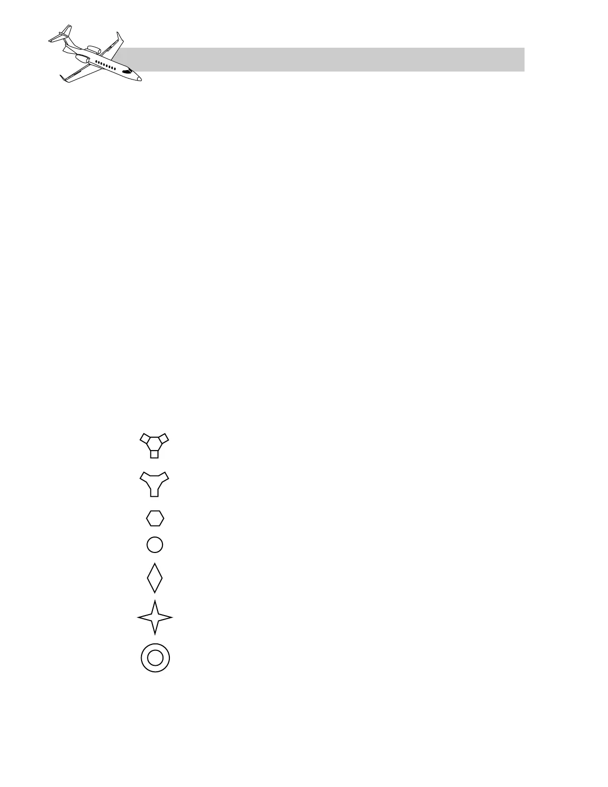
• FMS MAP/PLAN symbols are charac-
teristic to standard instrument charts and
to the Primus 1000 avionics system
(Figure 16-41).
• Waypoints are symbolized as four pointed
stars, positioned at the Latitude and
Longitude of geographical locations, ref-
erenced to the present position of the air-
plane. The total number of flight plan
waypoints allowed for display is 10 (in-
cluding the "FROM" waypoint). A way-
point can also be included as a
pseudo-VOR. A flight plan can follow a
pseudo-VOR display if the subsequent
waypoint records are connected way-
points.
• Background navigation aids (VOR, DME,
co-located VOR/DME) examples are il-
lustrated in Figure 16-37. The navaids
are derived through the FMS data base and
are positioned in relation to the FMS de-
termined present position. A maximum of
eight navaids will plot on the MFD (4
VORs and 4 NDBs). NAVAIDs may also
be included in the flightplan and are in-
cluded in the total waypoint count (max-
imum of 10). NAVAID displays are
selected or deselected with the NAV bezel
key on the MFD menu.
• Non-Directional Beacon (NDB) is sym-
bolized as an unfilled circle and repre-
sents the position of the NDB relative to
the airplane present position.
• Airports are displayed as a circle and rep-
resent the position of the airport symbol
relative to the present position. A maxi-
mum of four airports can be plotted on the
MFD. The airport identifier is displayed
to the right of the symbol. Airports dis-
plays are selected or deselected with the
APT bezel key on the MFD menu.
• Altitude Profile Points are displayed as
a diamond and represent the location for
a preplanned descent to a pre-determined
altitude. If they are included in the flight-
plan, they will be counted towards the
waypoint total. Disconnected altitude
profile points are limited to two.
LEARJET 45 PILOT TRAINING MANUAL
16-70
FOR TRAINING PURPOSES ONLY
FlightSafety
international