FT-107 Weighing Terminal, Technical Manual, Rev. 1.0.0, August 2019 Page 14 of 46
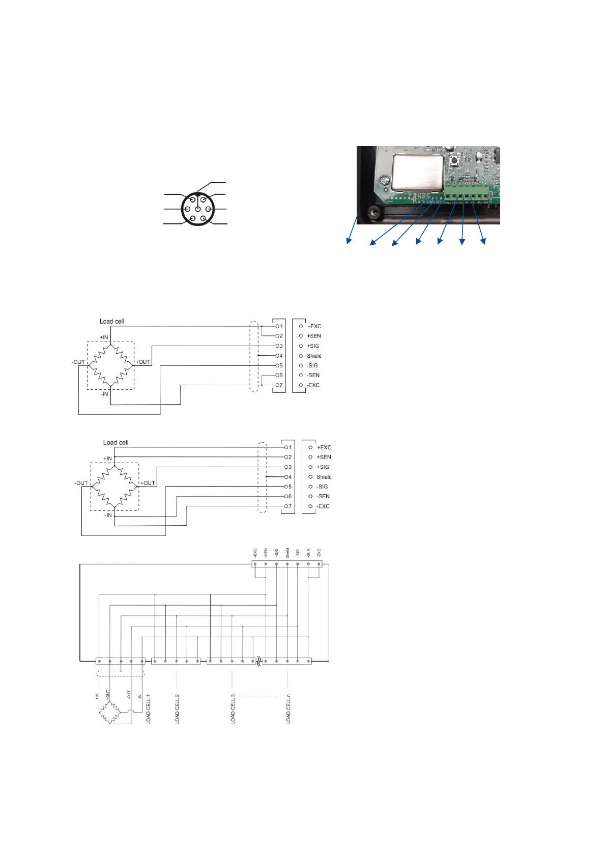
4.4.1 Load Cell Connection
To avoid damages, the load cell wiring should be made carefully before energizing the instrument. Load cell
connection details are shown in Figure 4.4. In 4-wire installations the sense and excitation pins with the same
polarity should be short circuited at the connector side. If you have junction box in your system, use 6 wire
cable between FT-107(S) and the junction box, and short circuit these pins at junction box for better
performance.
FT-107 (rear view) FT-107S
Figure 4.3- The load cell connector
Figure 4.4 – The load cell and junction box connection
Warning: Always connect Sense pins to Excitation pins for 4 wire connection. Non-connected sense pins
may cause the wrong Excitation voltage measurement and create an accuracy problem.
Warning: Connect the load cell cable shield to the housing (recommended to increase the EMC immunity
against disturbances) or shield pin of the load cell connector.