Page 26 CWT Compact Touch Installation and Maintenanace Manual Issue 13
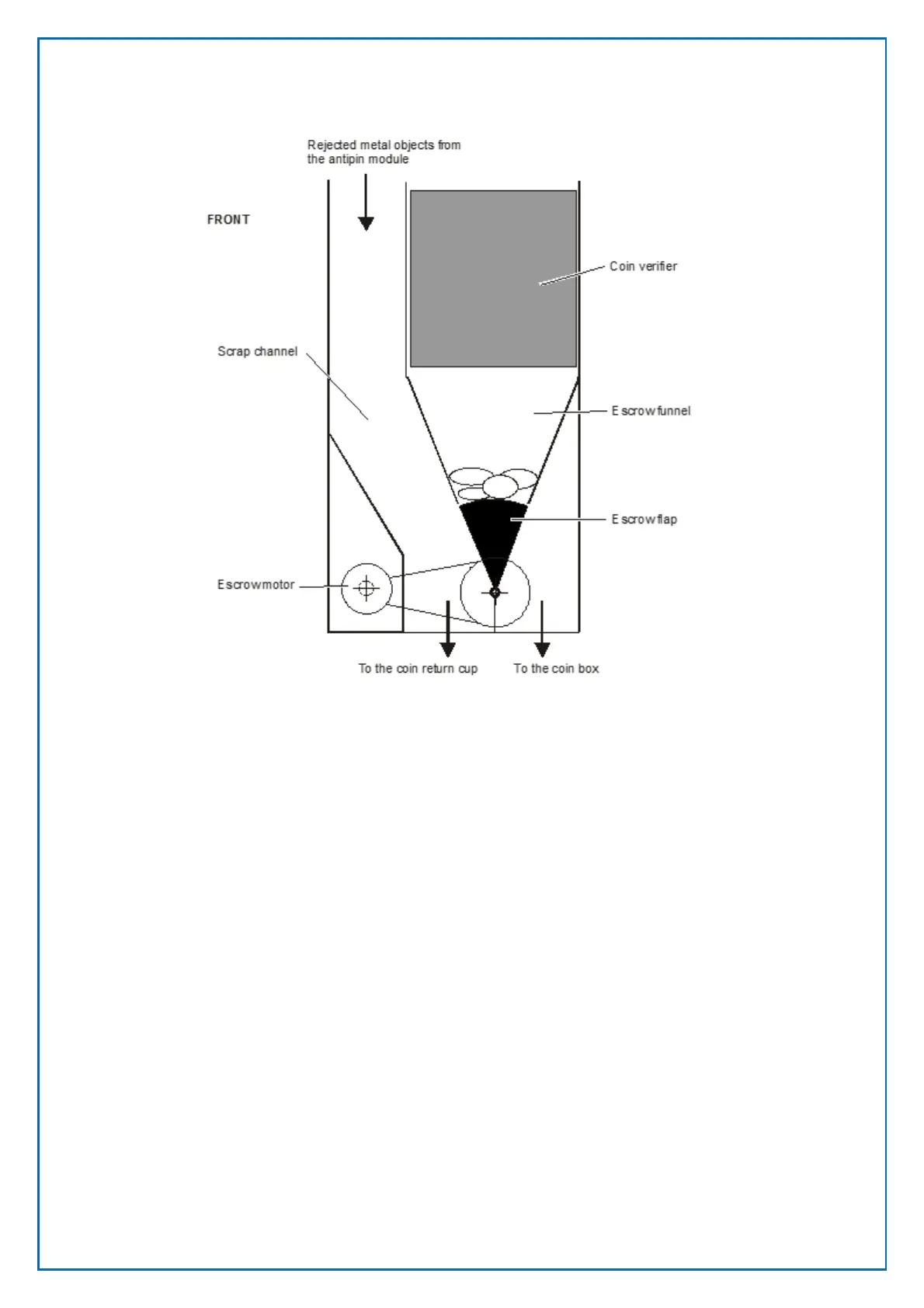
The figure above shows the coin unit as seen from the terminal’s right side.
To the left is the scrap channel through which any objects rejected by the anti-pin
module or the coin verifier will fall into the coin return cup.
Below the coin verifier is the escrow that consist of a funnel, a flap and a DC
motor (escrow motor).
The flap can be rotated to the left or right by the motor via a toothed belt and a
pulley attached to the flap. The pulley has a small permanent magnet mounted
close to its outer edge. There is a printed circuit board, named coin handling
board, mounted on the left side of the coin system module (not shown in the
above figure). This board has three Hall- effect sensors that detect the position of
the permanent magnet, and thus the position of the pulley and the flap.
The figure above shows the escrow flap in home position, that is, the position it
has until the customer either accepts or cancels the purchase. Any inserted coins
remain inside the escrow funnel.
In the figure below the customer has accepted the purchase and the escrow
motor have turned the flap to the Accepted Purchase position. The coins fall into
the coin box.
Figure 11, Escrow in home position.