Limitorque MX Maintenance and Spare Parts FCD LMENIM2314-00 – 07/08
22
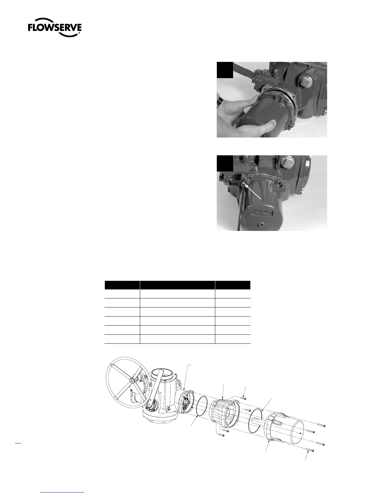
STEP 7
Push the rotor shaft onto the protruding
worm shaft, aligning the rotor shaft slots with
the worm shaft pin. Slide the motor housing
spigot/pilot into the actuator housing.
7
STEP 8
Fit the four screws (#1-14) into the motor
subassembly mounting holes and tighten.
8
1-14
4.1.3 Removal and mounting of MX-140 motor
(40 RPM and greater)
Table 4.2 – Motor Parts List
Part Number Description Qty.
1-14 Socket head cap screw 4
1-15 O-ring 1
4-7 Motor 1
4-8 Adapter, motor 1
4-9 Socket head cap screw 4
4-10 O-ring 1
Figure 4.2 – Motor and Adapter (MX-140)
MAIN UNIT ASSEMBLY
4-8
1-14
4-10
1-15
4-7
4-9
Swanson Flo | 800-288-7926 | www.swansonflo.com