ROTADISK Pneumatic Actuator RD & RDF
Operating Manual – BA3002 EN
5 Installation
Page 38 of 79
Direct installation is possible when the dimensions of the drive shaft and the ISO
flange of the ROTADISK Pneumatic Actuator match those of the valve (e. g. ball
valve) and the ISO flange of the valve has a through-hole. Differences in dimensions
to transmission shaft of the valve could be compensated by optionally available
reducers.
Installation by means of a console is necessary when the differences in dimensions
between the drive shaft of the ROTADISK Pneumatic Actuator and the transmission
shaft of the actuator cannot be compensated by reducers or the ISO flanges do not
match. This installation alternative can also be used for high/low medium
temperatures or thick pipe insulations.
5.3 Installing ROTADISK Pneumatic Actuator on the Valve
The ROTADISK Pneumatic Actuator has a standardised DIN/ISO 5211 valve interface
on which valves can be mounted with the aid of installation kits in accordance with
EN 15081.
For valve installation, see also the enclosed valve product information (e. g.
operating manual).
Important for the correct switching of the valve by the ROTADISK Pneumatic
Actuator is that the valve and the pneumatic actors have an identical basic setting.
Contact the Quick Response Center (QRC) of Flowserve Flow Control GmbH for
installation support.
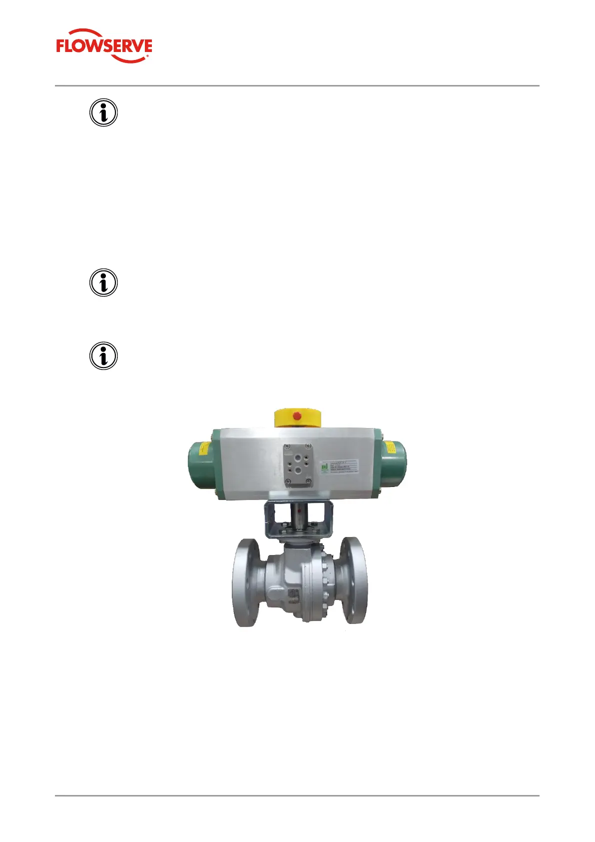
Figure 3: ARGUS Ball Valve with installed
ROTADISK Pneumatic Actuator RDF
(closed ball position)