Multifunction Tester
Measurements
45
RCD Tripping Current Measurements
This test measures the RCD tripping current as you apply a test current and then gradually
increase the current until the RCD trips. You can use the test leads or mains test cord for this
test.
Note
For RCD type B or S-type B all three test leads are required.
XW Warning
To prevent possible electrical shock, fire, or personal injury:
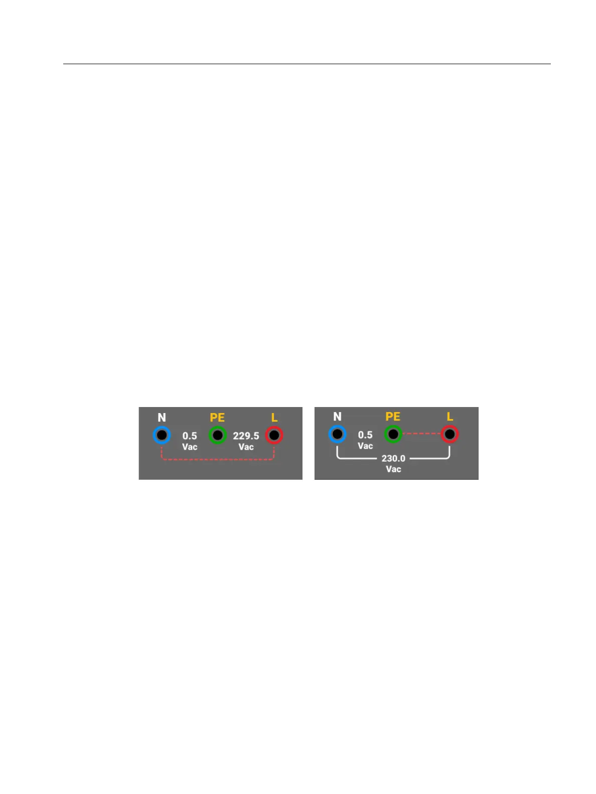
Test the connection between the N-conductor and earth before you start the test.
A voltage between the N-conductor and earth may influence the test.
Leakage currents in the circuit that follows the residual current protection device
may influence measurements.
The displayed fault voltage relates to the rated residual current of the RCD.
Potential fields of other earthing installations may influence the measurement.
If the L and N terminals are reversed, the Tester automatically swaps them internally and
continues tests. If the Tester is configured for UK operation, tests stop and you must
determine why the L and N are swapped. The terminal indicator icons indicate this condition.
To measure RCD tripping current:
1. Select the I
ΔN
mode.
2. Select the RCD current rating (10, 30, 100, 300, 500, 1000 mA). If the RCD has a special
nominal current setting other than the standard options, use a custom setting with the Var
mode.
3. Select the RCD type:
AC current to test type AC (standard AC RCD) and type A (pulse-DC sensitive RCD)
Half-wave current to test type A (pulse-DC sensitive RCD)
Delayed response to test S-type AC (time delayed AC RCD)
Delayed response to S-type A (time delayed pulse-DC sensitive RCD)