Multifunction Tester
Measurements
49
Earth Resistance Measurements (1673 FC and 1674 FC)
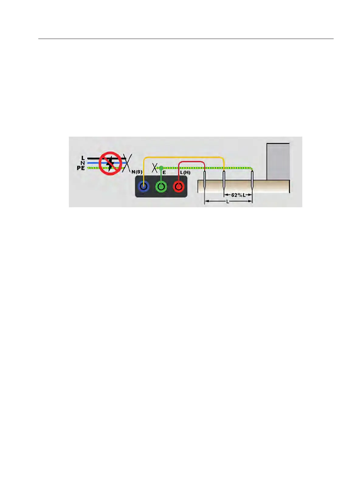
The earth resistance test is a 3-wire test that has two test stakes and the earth electrode
under test. This test requires an accessory stake kit. Connect as shown in Figure 21.
Best accuracy is achieved with the middle stake at 62 % of the distance to the far stake.
The stakes should be in a straight line and wires separated to avoid mutual coupling.
Disconnect the earth electrode under test from the electrical system as you do the test.
Do not measure Earth resistance on a live system.
Figure 21. Earth Resistance Test Connection
To measure earth resistance:
1. Select the R
E
mode.
2. Press and release
T.
3. Wait for the test to complete:
The primary display shows the earth resistance reading.
Voltage detected between the test rods shows in the secondary display. If >10 V, the
test is inhibited.
If the measurement is too noisy, a warning message shows on the display. The
measured value accuracy is degraded by the noise.
If the probe resistance is too high, a warning message shows on the display. To help
reduce probe resistance, push the test stakes further into the earth or apply water to
the earth around the test stakes.
This measurement can also be done with a Fluke 1630-2 FC Earth Ground Clamp. A Bluetooth
Low Energy (BLE) connection to this clamp is configured in the main menu. When an Earth
Ground Clamp is connected, the Tester shows the clamp measurement on the display.
Tip: Tap
p to see the connection diagram and more information on screen.