1672/1673 FC/1674 FC
Users Manual
48
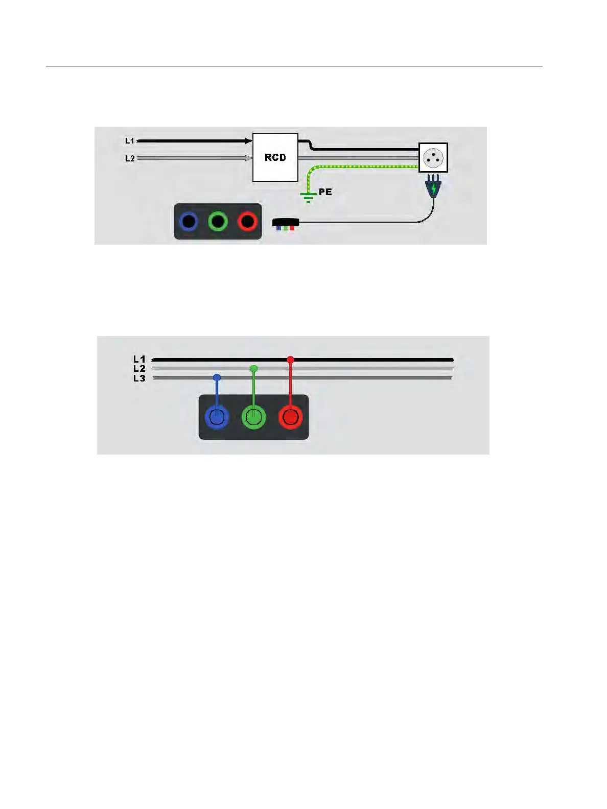
If RCD does not trip, use the test lead configuration shown in Figure 19.
Figure 19. Single Test Lead Configuration
Phase Rotation Tests
Use the connection shown in Figure 20 for a phase rotation test connection.
Figure 20. Phase Rotation Test Connection
To d o a p h a s e ro t a t i o n t e s t :
1. Select the Phase mode.
2. The primary display shows:
L1-L2-L3 for correct phase rotation 4.
L3-L2-L1 for reversed phase rotation 3.
0 when insufficient voltage is sensed.
Tip: Tap
p to see the connection diagram and more information on screen.