Diagnostic Testing and Troubleshooting
Power Supply Troubleshooting
5
5-11
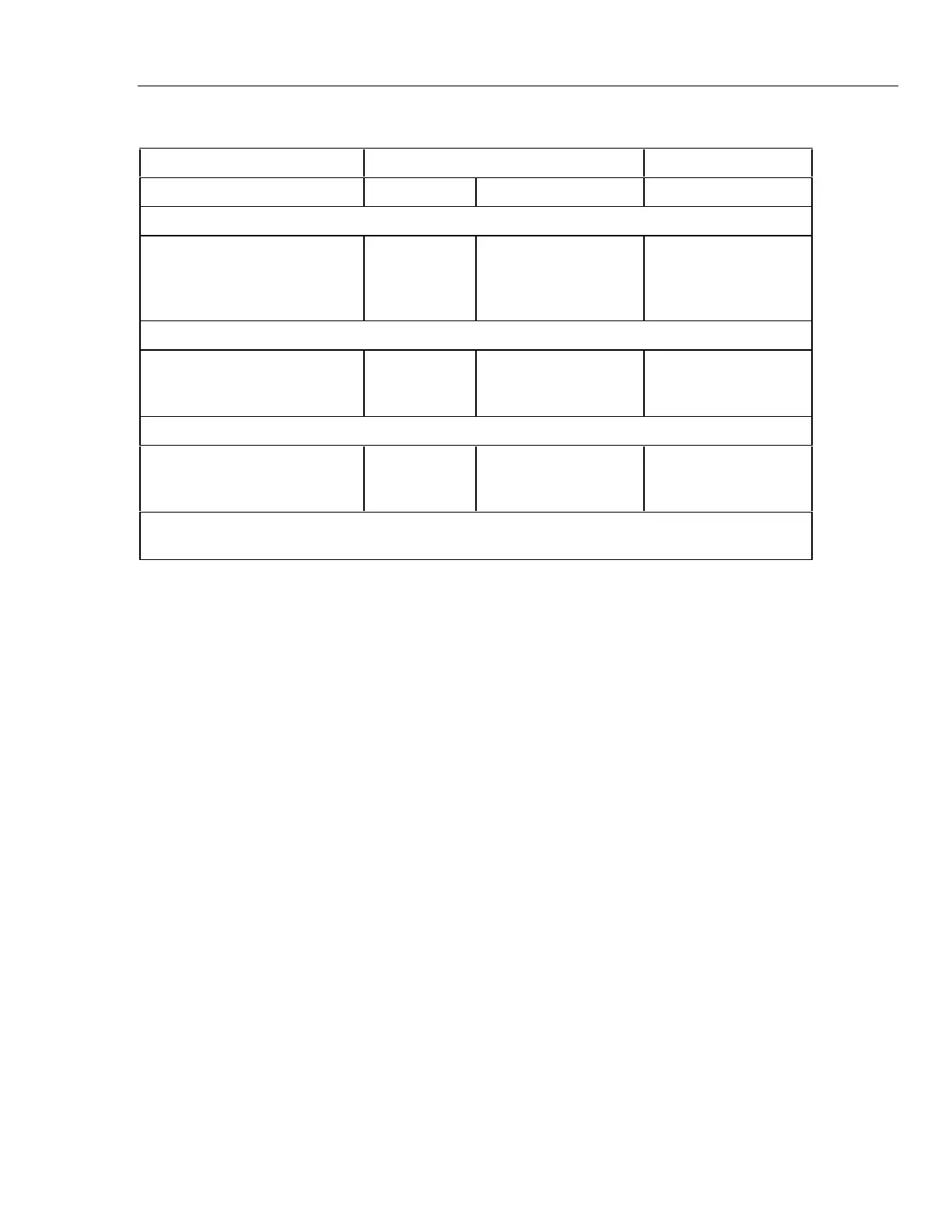
Table 5-2. Power Supplies
Supply Name Measure Supply Range
From: To:
Main PCA (In-Guard Circuits)
VDD
VSS *
+VAC
-VAC
A1TP10
A1TP12
+VAC
-VAC
COM, A1R2, or A1R3*
COM, A1R2, or A1R3
COM, A1R2, or A1R3*
COM, A1R2, or A1R3*
4.95 to 5.45 V dc
-4.95 to -5.45 V dc
4.7 to 5.35 V
-4.7 to -5.35 V
Main PCA (Out-Guard Circuits)
VCC
VEE
VLOAD
A1TP18
A1TP16
A1TP15
A1TP17
A1TP17
A1TP17
4.85 to 5.35 V dc
-5.0 to -6.0 V dc
-28.5 to -32.0 V dc
Display PCA (Out-Guard Circuits)
VCC
VEE
VLOAD
A2U1-21
A2U1-4
A2U1-5
A2TP3 or A2U1-42
A2TP3 or A2U1-42
A2TP3 or A2U1-42
4.85 to 5.35 V dc
-5.0 to -6.0 V dc
-28.5 to -32.0 V
* These points are at ’Common.’ ’Ground’ is also used in the meter, but in relation to Out-
Guard circuits only. For example, the A2 Display PCA uses ’Ground’.
5-7. 5-Volt Switching Supply
Use an oscilloscope to troubleshoot the 5-volt switching supply. Check the waveform at
either A1U11, pin 6 (switch transistor collector) or A1T1, pin 2 to determine the loading
on the 5-volt switching supply.
• Normal load:
The waveform is a square wave with a period of approximately 20 to 25 us and an
ON (voltage is low) duty ratio of about 0.35 when the line voltage is about 120 V ac.
The amplitude is usually about 15 V p-p. The positive-going edge of the waveform
will be "fuzzy" as the duty ratio is varying to compensate for the ripple of the raw
supply and the pulsing load due to the switching of the inverter. See Figure 5-2.
• Very Light or No Load:
The OFF interval (voltage is high) part of the waveform will have a damped ringing
sine wave of 2 to 10 cycles.
• Heavy Load or Shorted:
The waveform is a square wave with a very low ON duty ratio (approximately 0.1.)
If no square wave signal is present, the functioning of the oscillator can be checked
by looking at the waveform at A1U11, pin 3. Use the oscilloscope with ac coupling
to make this measurement. This waveform should be a sawtooth signal with an
amplitude of 0.5 V p-p and a period of approximately 20 to 25 µs.
The output current of the 5-volt switching supply can be determined by measuring
the voltage across the current limit current sense resistors (A1R47, A1R48, A1R49).
The current shunt is approximately 0.167 ohms. With line voltage at 120 V ac,
typical voltages across the current sense resistors are as follows:
• Meter without options: 42 mV
• Meter with IEEE-488 Interface Option: 72 mV