Theory of Operation
Detailed Circuit Description
2
2-13
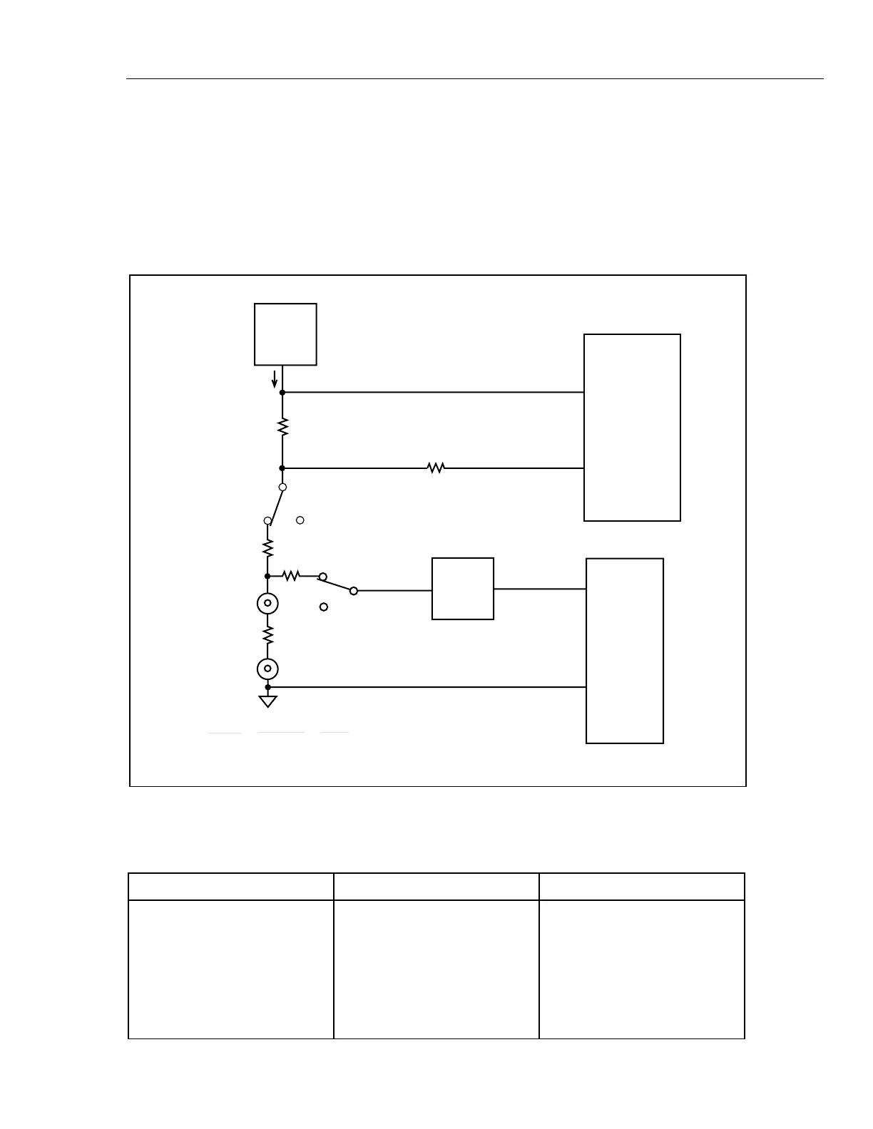
Depending on the range, S3, S6, S9, S13, or S15 connects the Analog Measurement
Processor ohms voltage source to a reference resistor. The resulting current passes
through the reference resistor, A1K2, the protection resistors A1RT1 and A1R5, and the
unknown resistance. The a/d converter integrates with the voltage across the unknown
through the OVS input (pin 23). For DE- integrate reference, the a/d converter uses the
voltage across the reference resistor through RRS (pin 13) and Ohms Reference High
through S5 (pin 21), S14 (pin 19), S17 (pin 16), S11 (pin 15) or S8 (pin 14). Reference
resistances are identified in Table 2-3.
OHMS
VOLTAGE
SOURCE
A/D
INTEGRATE
REFERENCE
LOW
HIGH
A1R9
A1Z1
REFERENCE
RESISTOR
R
REF
+
_
VR
REF
A1K2
A1RT1&A1R5
A1K1
V Ω
COM
UNKNOWN
RESISTOR
ACTIVE
FILTER
A/D
INTEGRATE
UNKNOWN R
HIGH
LOW
I
X
A1R6 & A1R7
R
X
VR
X
VR
X
VR
REF
=
I
R
X
I
X
R
REF
R
REF
R
X
=
X
+
-
qb04f.eps
Figure 2-4. Ohms Simplified Schematic
Table 2-3. Reference Resistance
Range Voltage Source A1Z1 Reference Resistor
100 Ω /300 Ω 3 V 1 kΩ
1000 Ω/3 kΩ 1.3 V 10.01 kΩ
10 kΩ/30 kΩ 1.3 V 100.5 kΩ
100 kΩ/300 kΩ 1.3 V 1 MΩ
1000 kΩ/3 MΩ/10 MΩ 1.3 V 10 MΩ
30 MΩ 3 V 10 MΩ
100 MΩ/300 MΩ 3 V 10 MΩ
Diode Test 3 V 1 kΩ