Option -01 Battery Pack
Troubleshooting
7
7-13
Red
Battery ConnectorsBlack
View from bottom of instrument
qb37f.eps
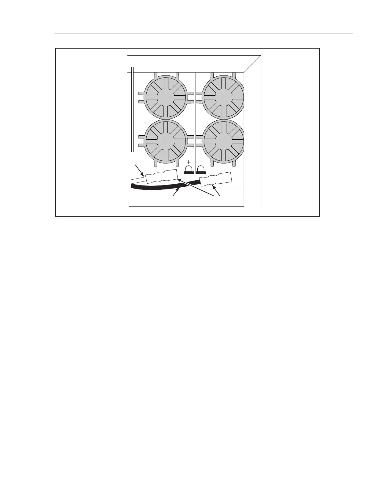
Figure 7-6. Unplugging the Battery Pack Connectors
7-19. Troubleshooting
Troubleshooting can be facilitated by removing the Battery Pack Option and connecting
the Battery PCA with an extender cable (Fluke Part Number 854245). Refer to the
removal instructions provided earlier in this chapter.
With the meter off (but plugged into line power), check for approximately 16 V dc (at
120V ac line) raw dc supply between the ground test point and the cathode of either
A1CR2 or A1CR3. If necessary, check for transformer secondary voltage of
approximately 24 V ac.
Use an oscilloscope to trace the waveforms associated with the switching power supply.
• With the line voltage at 120 V ac, check the waveform at the drain of FET Q5. This
signal should be a 25 V p-p square wave, with the negative part at zero volts, a
period of 20 to 25 µs, and an ON duty ratio of .20 to .50. This square wave may
exhibit a damped sine wave (two to ten cycles) ringing on the trailing half of the
positive portion. The sine wave amplitude should be from 10 to 20 V p-p.
• Check for a 15 V p-p square wave at the gate of Q5.
• Check for a 14 V p-p square wave at U4-5.
• Check for a 0.5 V p-p sawtooth waveform (with a period of 20 to 25 µs) at U4-3.
Make sure that the oscilloscope is ac-coupled for this measurement.
Troubleshoot other sections of the Battery Pack Option assembly by making dc voltage
measurements. For circuit common, use the GND test point on the main circuit board or
the common end of R30 on the Battery Pack PCA. Note that the battery pack negative
terminal is not connected to common when the low battery disconnect circuit turns off
Q2.