Theory of Operation
Detailed Circuit Description
2
2-23
kΩ (nominal) pull-down to the -30 V dc supply. These pull-downs are internal to the
Display Controller.
The output port, P63, of the Display Controller, is used as a grid control output for
GRID(10), of the vacuum-fluorescent display. A high voltage output, from P63, is
provided with a 10 kΩ resistor (A2R1), and PNP transistor (A2Q1) provide an active
driver to the +5 V dc supply and a passive 47 kΩ pull-down (A2R4) to -30 V dc.
The Display Controller drives the vacuum-fluorescent display in a multiplexed manner
by strobing each grid individually while the segment data for that display area is
presented on the anode outputs. Each grid is strobed for approximately 427
microseconds every 5.368 milliseconds, resulting in each grid on the display being
strobed about 170 times per second. The grid strobing sequence is from GRID(0) to
GRID(10), which results in right-to-left strobing of grid areas on the display. Figure 2-10
shows grid control signal timing.
The single grid strobing process involves turning off the previously enabled grid,
outputting the anode data for the next grid, and then enabling the next grid. This
procedure ensures that there is some time between grid strobes so that no shadowing
occurs on the display. Figure 2-11 describes the timing relationship between an
individual grid control signal and the anode control signals.
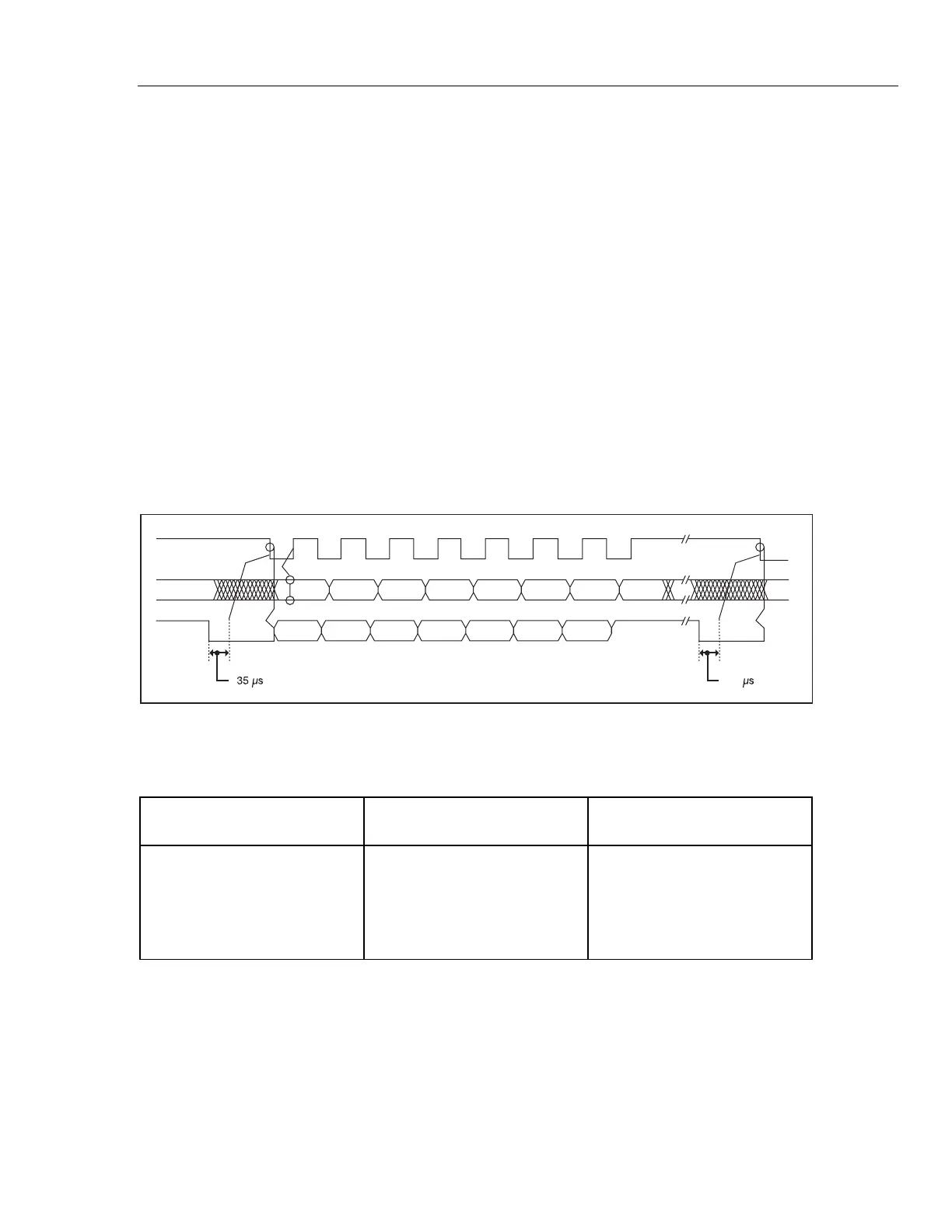
BIT 7 BIT 6
DSCLK
Clear to receive
DISTX
DISRX
BIT 5 BIT 4 BIT 3 BIT 2 BIT 1 BIT 0
BIT 7 BIT 6 BIT 5 BIT 4 BIT 3 BIT 2 BIT 1 BIT 0
Clear to receive
35
qb09.eps
Figure 2-9. Command Byte Transfer Waveforms
Table 2-6. Display Initialization Modes
A2TP4 Dtest* A2TP5 LTE* Power-Up Display
Initialization
1 1 All Segments OFF
1 0 All Segments ON (default)
0 1 Display Test Pattern #1
0 0 Display Test Pattern #2