Option -01 Battery Pack
General Maintenance
7
7-7
A.
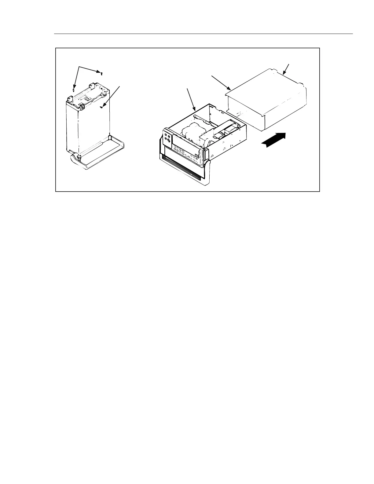
Mounting Screw (2)
Chassis
Case
Rear Bezel
Grounding Screw (2)
B.
qb14f.eps
Figure 7-2. Removing the Case
4. Remove the two #6-32 x 1/4" panhead Phillips screws securing the Battery Pack
Option (see Figure 7-4).
5. Carefully slide the Battery Pack Option out of the meter (as shown in Figure 7-4).
Do not pinch the wires running from the circuit board to the battery terminals.
Caution
To prevent damage to the meter when servicing the Main PCA,
unplug the battery pack ribbon cable at the Main PCA or
disconnect the wires to the battery pack.
7-13. Installation
Use the following instructions to install the Battery Kit Option. Refer to the Instruction
Sheet (PN 856013 - supplied with the Battery Kit) for the more detailed instructions
required with an initial installation of the Battery Kit Option.
1. Make sure the meter is turned off and disconnected from line power.
2. With the meter disconnected from line power, discharge the power supply capacitor
by turning the meter on. After five seconds, turn the meter off.
3. Carefully slide the battery kit into the area reserved for it in the back of the meter (as
shown in Figure 7-4). Make sure that both the retaining slots line up and the
mounting holes mate. Do not pinch wires running from the circuit assembly to the
battery pack terminals.
4. Secure the battery kit with two #6-32 x 1/4" panhead Phillips screws.
5. Attach the flat, white connecting cable at the Battery Pack Option circuit board (see
Figure 7-3). The single blue line of the cable should be to the rear of the meter.
Align the plastic socket on the cable end, then seat it securely in place.
6. Reinstall the meter case to seat properly in the front panel. Attach the rear bezel with
the two panhead Phillips screws, and secure the case with the flathead Phillips screw
in the bottom.