45
Service Manual
2-14
V
A1C1
A1K3
mA
F1 F5
A1R2
10
A1AR1
+
_
A1Z2
1.111M
A1Z2
115.7
A1Z2 FEEDBACK
RESISTOR
A1Z2
2.776k
RMS
COVERTER
A1C7
A1R5 &
A1RT1
qb05f.eps
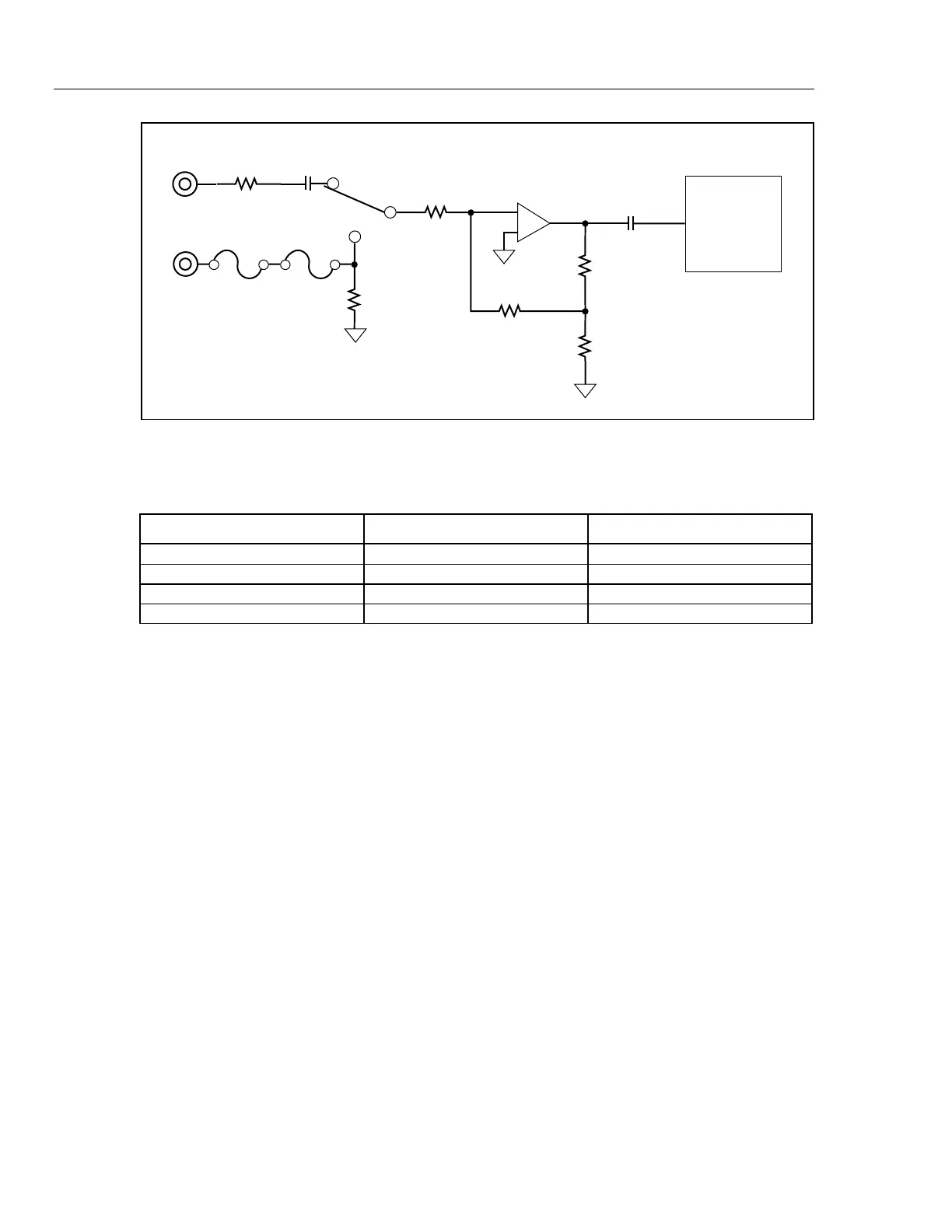
Figure 2-5. AC Buffer Simplified Schematic
Table 2-4. AC Volts Input Signal Dividers
Range (Drive Signal) A1Z2 Feedback Resistor Overall Gain
100/300 mV (ACR1) 111.1 kΩ 2.5
1000 mV/3 V (ACR2) 12.25 kΩ || 111.1 kΩ .25
10/30 V (ACR3) 1.013 kΩ || 111.1 kΩ .025
100/300/750 V (ACR4) 2.776 kΩ .0025
2-24. 100 M
Ω
and 300 M
Ω
Ranges
The 100 MΩ and 300 MΩ ranges perform a conductance reading; the mathematical
reciprocal of this reading is used as a display in ohms. The reference resistor (A1Z1, 10
MΩ) is integrated first, then the unknown resistance is used for DE- integrate reference.
2-25. AC Volts
AC voltage and ac current inputs are scaled by the ac buffer, then converted to a
representative dc voltage by the true rms ac-to-dc converter.
Refer to Figure 2-5. JFETs A1Q2 to A1Q8 switch the ranges of the buffer amplifier
A1AR1. The JFET drive signals, ACR1 to ACR4 (pins 5 to 8) turn the JFETs either on at
0 V or off at -VAC. The ratio of the feedback resistor to the 1.111-MΩ input resistor
divides the input signal by 10, 100, or 1000. These arrangements are summarized in
Table 2-4. This signal is then amplified by 25 using the 2.776-kΩ and 115.7Ωbuffer
output divider resistors. The A1Z2 111.1-kΩ feedback resistor is left in parallel with the
higher range feedback resistors. For the 300/750 V range, the 2.776-kΩresistor becomes
the feedback element. A1R15 and A1C2 compensate the 300-mV range of the ac buffer.
The ac signal is then routed to the rms converter by Analog Measurement Processor
switch S38. Capacitors A1C1, A1C7, A1A1C2, and A1A1C3 function as dc blocking
capacitors. A1A1R1 provides input bias current for the rms converter buffer, and
A1A1C1 is the converter’s averaging capacitor.
The rms converter output is divided down by 2.5 by A1Z4; A1R19 and A1C10 form the
passive filter for ac volts. Analog Measurement Processor switch S80 shorts A1R19 both
during ranging and in the fast measurement rate. Components A1R16, A1R17, A1C3,