45
Service Manual
5-22
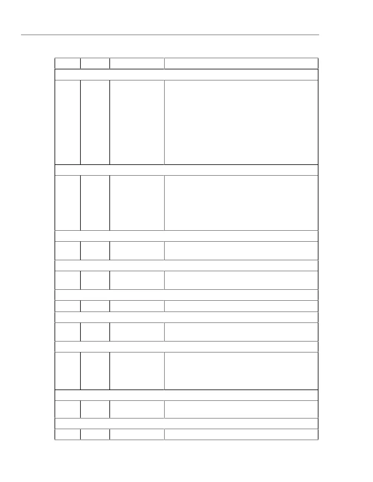
Table 5-6. Calibration Steps and Related Components
Step Range Input Related Components
VDC
1
2
3
4
5
6
7
8
9
10
100 mV
100 mV
100 mV
1000
mV
100 mV
300 mV
3 V
30 V
300 V
1000 V
0.0000 V
0.0900 V
-0.0900 V
0.9000 V
0.0900 V
0.2900 V
2.9000 V
29.000 V
290.00 V
1000.0 V
A1VR1, A1Z3
A1VR1, A1Z3
A1VR1, A1Z3
A1VR1
A1VR1, A1Z3
A1VR1, A1Z3
A1VR1, A1Z3
A1VR1, A1Z1, A1Z3
A1VR1, A1Z1, A1Z3
A1VR1, A1Z1, A1Z3
VAC
11
12
13
14
15
16
17
300 mV
300 mV
3 V
3 V
30 V
300 V
750 V
0.0290 V
0.2900 V
0.2900 V
2.9000 V
29.000 V
290.00 V
750.00 V
A1A1 A1VR1, A1Z2, A1Z3, A1Z4
A1A1 A1VR1, A1Z2, A1Z3, A1Z4
A1A1 A1VR1, A1Z2, A1Z3, A1Z4
A1A1 A1VR1, A1Z2, A1Z3, A1Z4
A1A1 A1VR1, A1Z2, A1Z3, A1Z4
A1A1 A1Z1, A1Z2, A1Z3, A1Z4
A1A1 A1Z1, A1Z2, A1Z3, A1Z4
DC mA
18
19
30 mA
100 mA
29.000 mA
100.00 mA
A1R2, A1VR1, A1Z3, A1F1
A1R2, A1VR1, A1Z3, A1F1
AC mA
20
21
30 mA
100 mA
29.000 mA
100.00 mA
A1A1, A1R2, A1VR1, A1Z2, A1Z3, A1Z4, A1F1
A1A1, A1R2, A1VR1, A1Z2, A1Z3, A1Z4, A1F1
DC A
22 10 A 10.000 A A1R3, A1VR1, A1Z3, A1F2
AC A
23
24
10 A
10 A
2.0000 A
10.000 A
A1A1, A1R3, A1Z4, A1F2
A1A1, A1R3, A1VR1, A1Z3, A1Z4, A1F2
Ohms
25
26
27
28
29
300 Ω
3 kΩ
30 kΩ
300 kΩ
3 MΩ
190.00 Ω
1.9000 kΩ
19.000 kΩ
190.00 kΩ
1.9000 MΩ
A1Z1, A1Z3
A1Z1, A1Z3
A1Z1, A1Z3
A1Z1, A1Z3
A1Z1, A1Z3
Continuity/Hysteresis Threshold
30
31
0.000 mV
20.00 mV
A1U1
A1U1
Frequency
32 2.000 V p-p 10 kHz A1Y1