Section 4: Using the Model 9100: AC Voltage Function 4.4-7
Final Width = 215mm
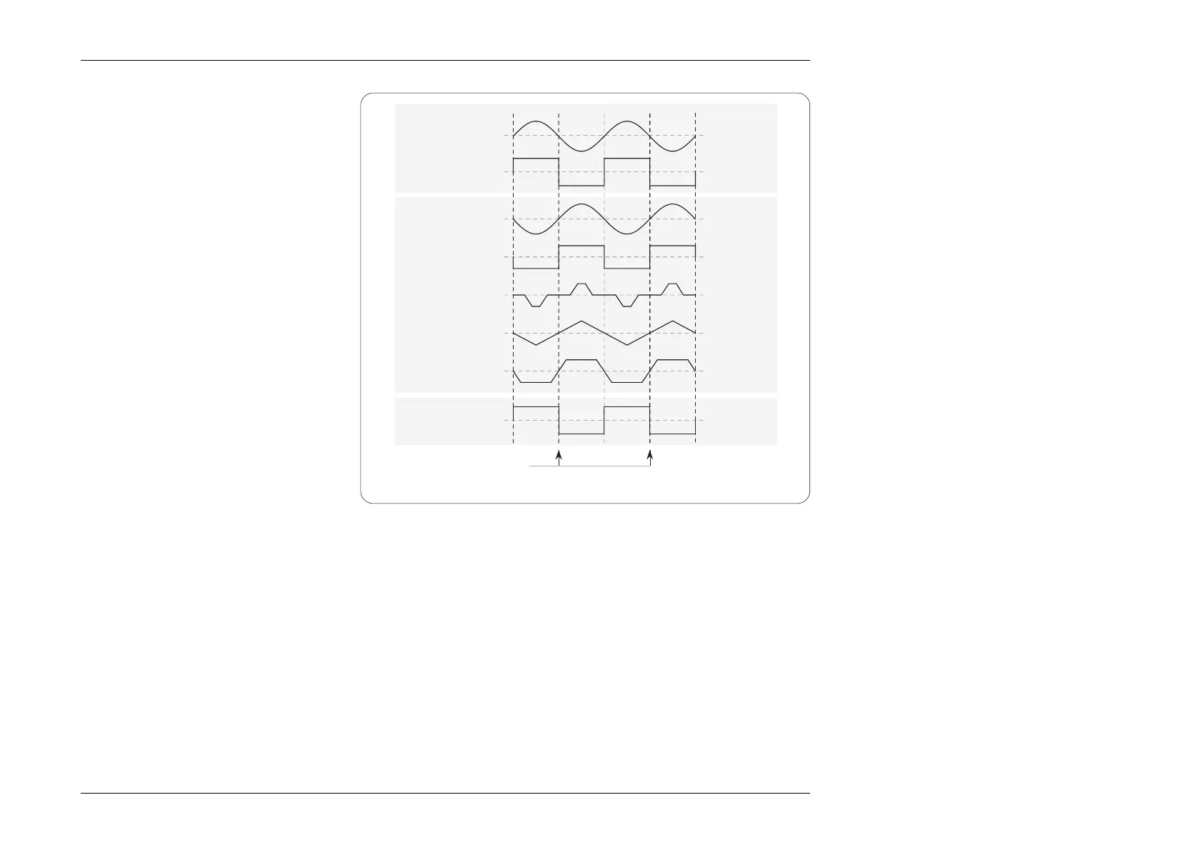
Reference Signal Output
The reference signal produced by a 9100 is a
wide pulse, compatible with TTL, between the
levels +0.5V and +4.5V, with its negative-
going edge coincident with the synchronization
points. (i.e. in phase with the 'PHASE LOCK
IN
' input, when applied).
4.4.3.6 Conditions for Operation
Same Frequency
For any two 9100 units (Master and Slave),
both must be set to the same frequency of
1kHz or lower, before the output of the
Driven unit is turned on.
Good Practice
In general, a slave unit will be well-behaved
if the synchronizing pulse is interrupted.
However, as the voltage increases above a
few hundred volts, and the frequency
decreases below 100Hz, synch. pulse
interruptions or shifts may cause transients
which result in operation of the protection
circuitry in the slave unit, automatically
turning its output off.
Sinusoidal
Reference
Square
Reference
Impulse
Triangular
Trapezoidal
PHASE LOCK
IN
Sine
Square
FRONT PANEL
OUTPUTS
(Zero Phase Shift)
PHASE LOCK
OUT
(Zero Phase Shift)
Synchronization Points
To avoid this, if one unit must be run at HVAC and LF, it should be assigned as Master unit if at all possible (e.g. in a system
where one unit outputs 250V AC at 60Hz, and another outputs 10A at 60Hz, then the latter should be assigned to the slave role).
If units must be run as slaves at HVAC and LF (such as in a six-unit 3-phase system), observe the precautions described in the
following paragraphs.
Change of Function — Reference 9100 Unit
If the Reference unit's function is changed from ACV, its reference output will go low. This will cause the Driven unit to unlock
and free-run, being most unlikely to remain in phase with the Reference unit. External control will be re-established when the
Reference unit is returned to ACV function (or placed in ACI function). At this time the Driven unit's phase will be switched
rapidly, creating transient disturbances in the output AC voltage unless it is switched off. The Driven unit's output must therefore
be turned OFF before the reference unit is returned to any AC function, (ACV or ACI).
Disconnection of Reference Cable
Disconnection of the cable from the Reference input ('
PHASE LOCK IN' on the rear panel) will also cause the Driven unit to
free-run, with resultant phase-shift of its output and possible transients when reconnected. Again, the Driven unit's output must
be turned OFF before the cable is reconnected.
Phase Locking and Output Waveforms