3-2 Section 3: Model 9100 Controls: Introduction to the Front Panel
Final Width = 215mm
sHi sLo
Hi Lo
I+ I-
!
1
23
456
789
0
—
E
OFF
ON Mode
Aux
Hz
Ω
A
V
A B C D E F CLR
GH I J KL
MN OP QR
ST UV WX
YZ
OUTPUT
1500Vpk
max
15Vpk
max
15Vpk
max
HIGH VOLTAGE
DANGER
_
/
!
W
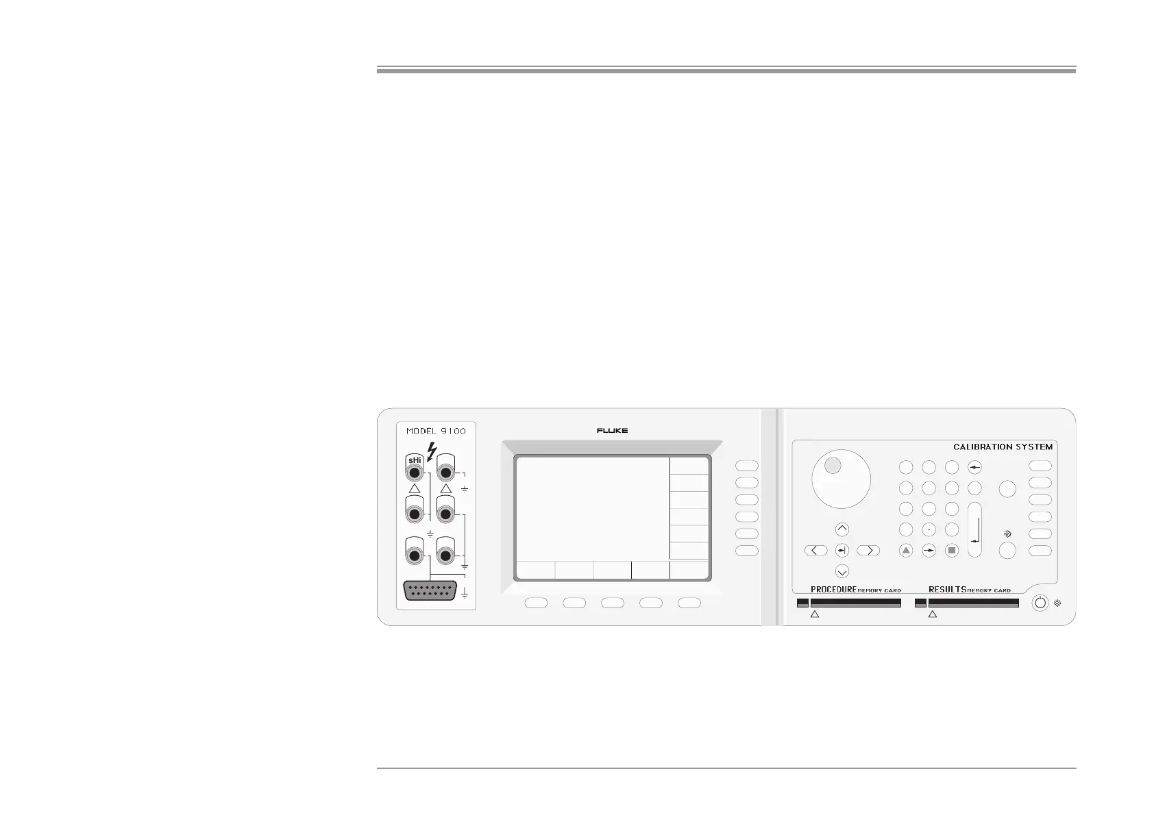
The front panel is divided into three main areas:
Center: A 'Menu' and 'Output Display' LCD screen, with grouped soft keys.
Right: A control panel, used to select and adjust operational Functions and Modes, with two slots to accept memory cards.
Left: Output Terminals, with a 'D-type' connector for functions with special guarding, screening and material requirements.
These features are described in the following paragraphs.
3.2 Introduction to the Front Panel
3.2.1 Local and Remote Operation
3.2.1.1 Manual Calibration of UUT Meters and Multimeters
Because the main role of the 9100 is to calibrate instruments (UUTs) which are themselves manually operated, most users will find
it convenient to control the 9100 at the same level. The front panel presents the operating interface necessary for manual control
of the 9100 output.
3.2.1.2 Remote Calibration of the 9100 Itself
The 9100 itself must periodically be verified or calibrated against suitable traceable standards. These processes are available
manually (Sections 9 & 10 — Volume 2), but to gain the advantages of simplicity and throughput provided by automated procedures,
the 9100 also incorporates a remote interface (IEEE-488.2/SCPI protocol). Its main use is to communicate with programmable
standards such as the Model 4950 Multifunction Transfer Standard, under the direction of external MTS Control Software. The
remote interface is described in Section 6 (Volume 2).
For the purposes of this section, the remote interface can be ignored.
3.2.1.3 General Arrangement of Front Panel Controls