2-4 Section 2: Installing the Model 9100
Final Width = 215mm
2.7 Preparation for Operation
Note: Refer to the Model 9100 General Specifications, including Environmental Conditions: Volume 2 of this handbook, Section
7, sub-section 7.1.
Before preparing the Model 9100 calibrator for operation, note the danger warning:
DANGER
THIS INSTRUMENT IS CAPABLE OF DELIVERING A LETHAL ELECTRIC SHOCK. THE FRONT PANEL
TERMINALS ARE MARKED WITH THE ABOVE 'FLASH' SYMBOL TO WARN USERS OF THIS DANGER.
UNDER NO CIRCUMSTANCES TOUCH ANY INSTRUMENT TERMINAL UNLESS YOU ARE FIRST SATISFIED
THAT NO DANGEROUS VOLTAGE IS PRESENT.
Caution: If the equipment is used in a manner not specified by the manufacturer, the protection provided by the equipment may
be impaired.
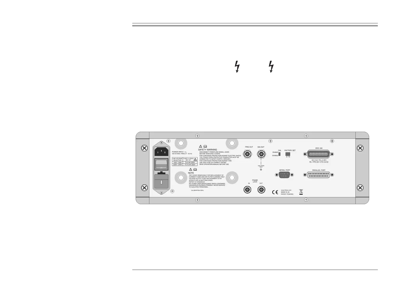
Other than the main output terminals and the D-type signal output socket, the connections to the 9100 are via the rear panel:
9100 Rear Panel