2-10 Section 2: Installing the Model 9100
Final Width = 215mm
2.8 Connectors and Pin Designations
112
1324
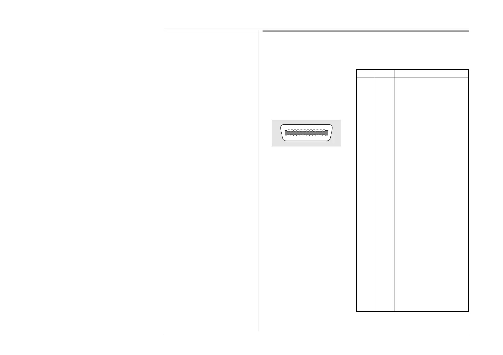
2.8.1 IEEE-488 Input/Output Socket J101 (Rear Panel)
This 24-way input/output connector
on the rear panel, which is labelled
IEEE-488, is directly compatible
with the IEEE-488 and IEC-625
Interface Bus standards.
Pin Layout
Pin Designations
Pin No. Name Description
1 DIO 1 Data Input Output Line 1
2 DIO 2 Data Input Output Line 2
3 DIO 3 Data Input Output Line 3
4 DIO 4 Data Input Output Line 4
5 EOI End or Identify
6 DAV Data Valid
7 NRFD Not ready for Data
8 NDAC Not Data Accepted
9 IFC Interface Clear
10 SRQ Service Request
11 ATN Attention
12 SHIELD Screening on cable (connected
to Safety Ground)
13 DIO 5 Data Input Output Line 5
14 DIO 6 Data Input Output Line 6
15 DIO 7 Data Input Output Line 7
16 DIO 8 Data Input Output Line 8
17 REN Remote Enable
18 GND 6 Ground wire of twisted pair with
DAV
19 GND 7 Ground wire of twisted pair with
NRFD
20 GND 8 Ground wire of twisted pair with
NDAC
21 GND 9 Ground wire of twisted pair with
IFC
22 GND 10 Ground wire of twisted pair with
SRQ
23 GND 11 Ground wire of twisted pair with
ATN
24 0V_F Logic Ground (Internally
associated with Safety Ground)