Section 2: Installing the Model 9100 2-9
Final Width = 215mm
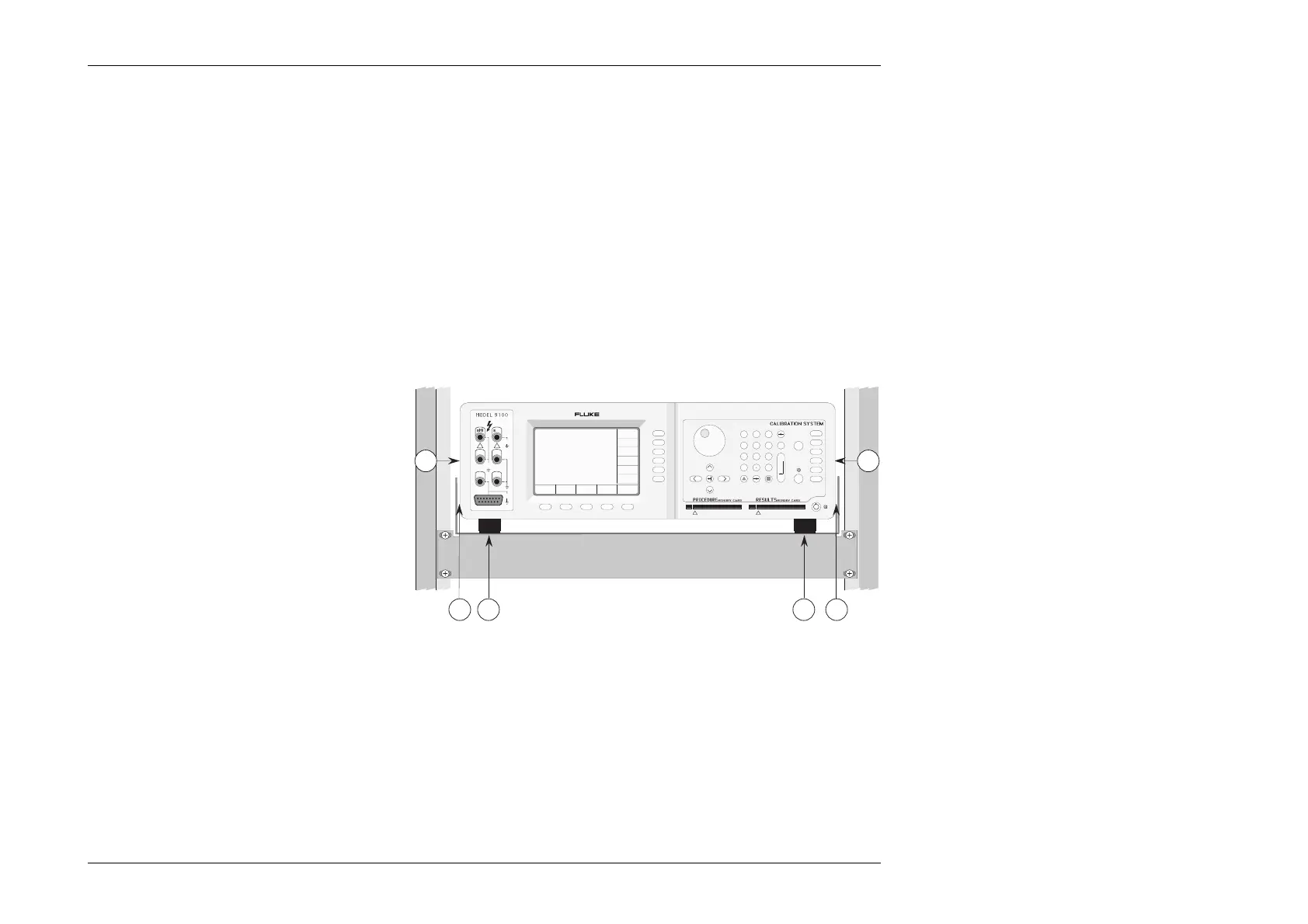
Setting the Calibrator on the Mounting Tray
1. Ensure that the feet (Z) are still fixed to the
bottom of the calibrator case (this provides the
necessary airflow path).
2. Slide the calibrator on to the tray, lining up the
front panel with the front of the cabinet.
3. Equalize the lateral clearances (Y) between the
calibrator and the tray sides.
Indication of Inadequate Cooling Airflow
In the event of the internal temperature rising to a
point at which the calibrator specification may be
invalidated, a warning message will appear on the
screen: "Over temperature".
Z Z
X X
sHi sLo
Hi Lo
I+ I-
!
1
23
456
789
0
—
E
OFF
ON Mode
Aux
Hz
Ω
A
V
A B C D E F CLR
GH I J KL
MN OP QR
ST UV WX
YZ
OUTPUT
1500Vpk
max
15Vpk
max
15Vpk
max
HIGH VOLTAGE
DANGER
_
/
!
Y Y