2-8 Section 2: Installing the Model 9100
Final Width = 215mm
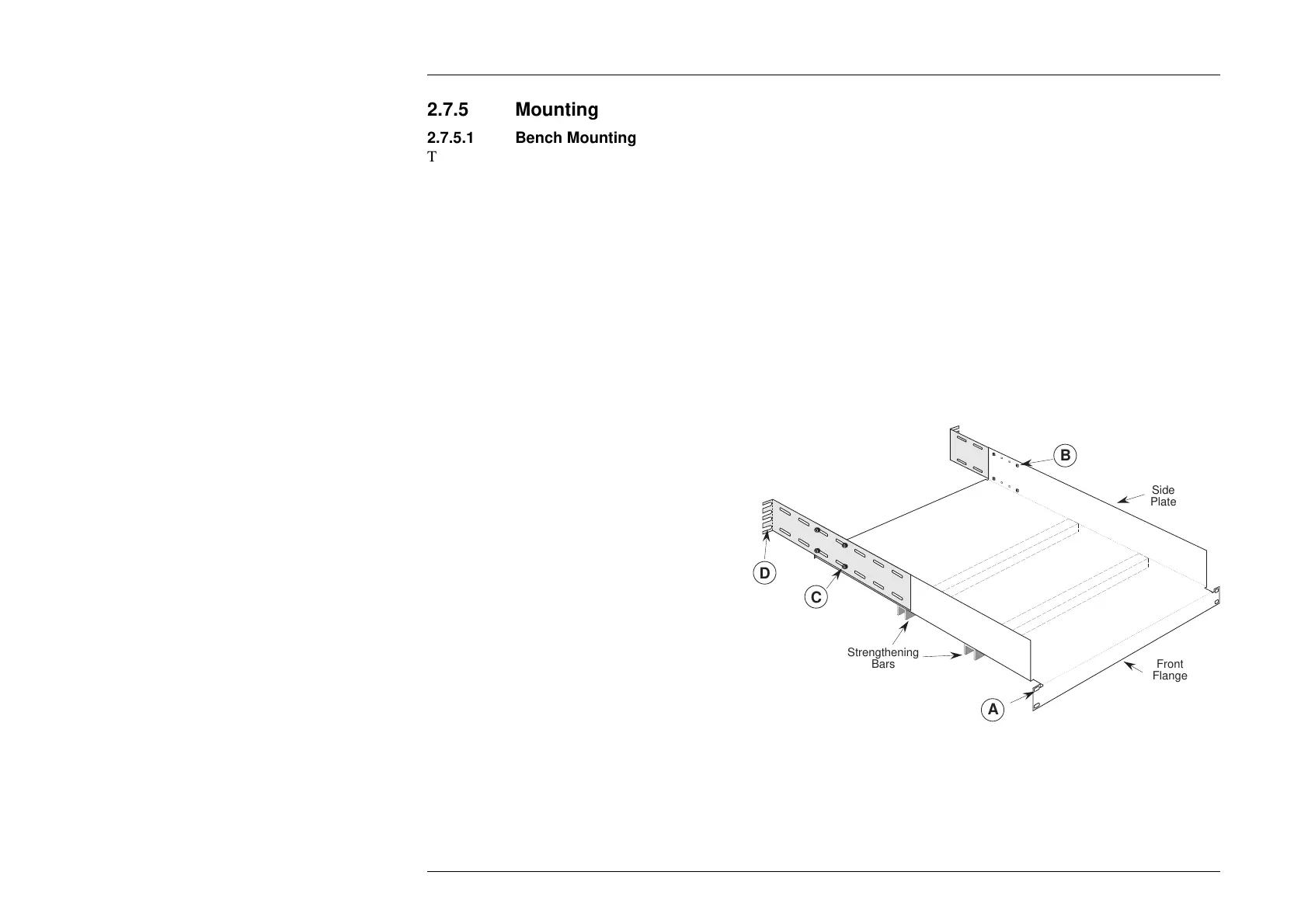
A
Strengthening
Bars
C
B
D
Front
Flange
Side
Plate
2.7.5 Mounting
2.7.5.1 Bench Mounting
The instrument is fitted with four plastic feet and a tilt stand. It can stand flat on a bench, positioned so that the cooling-air inlet
on the right side and exhaust apertures on the left side are not obstructed. It is recommended that at least 30cm (12 inches) of free
space be allowed on both sides. The front can be tilted upward for ease of viewing.
2.7.5.2 Rack Mounting (Option 90)
For a Model 9100 Calibrator supplied with Option 90 Rack Mounting Kit, the following fixing instructions must be observed in
order to ensure a successful installation:
Preliminaries
N.B. The Calibrator must not be rack-mounted into a totally-enclosed, unventilated cabinet. The internal cooling air intake is on
the right side about halfway to the rear; the air is exhausted from the left side. There must be sufficient clearance between
each calibrator ventilator port, and its adjacent solid cabinet sidewall (at points X), of at least 6cm.
Fixing the Mounting Tray to the Cabinet
1. Secure the strengthening channel bars to the
bottom of the tray as shown, using the eight M4
countersunk screws provided.
2. Measure the depth of the cabinet from front to
rear attachment strips.
3. Set the depth of the mounting tray (A - D) to fit
the cabinet, fixing the rear attachment brackets
to the sides of the tray. Use the eight M4
pozipan screws (B) on the inside and M4
nylock nuts (C) on the outside, through holes in
the tray sides and slots in the brackets, to secure
the brackets as shown. For cabinets with very
shallow depth, the brackets may be reversed
(with caution).
4. Offer up the tray into the cabinet (it may be
necessary to tilt the tray sideways) and attach
the brackets at D and front flange at A to the
cabinet strips using the eight M6 pozipan
screws, washers and cage nuts provided (for
some types of cabinet, it may be necessary to
use the appropriate cabinet screws).
Do not, under any circumstances, attach the
tray only at the front flange.
5. Adjust the position of the tray laterally to equalize the clearance between
the tray sides and the cabinet sidewalls.
Secure the cabinet screws at A and D.