Section 2: Installing the Model 9100 2-11
Final Width = 215mm
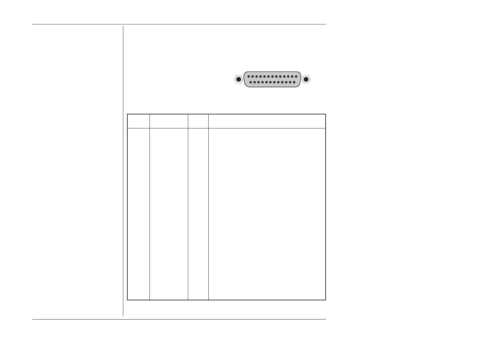
2.8.2 Parallel Port J103 (Rear Panel)
This 25 way D-Type socket is located
beneath the IEEE-488 connector on the
rear panel. Its connections are similar to
the 25-way printer port on PCs, carrying
control and data for an external printer as
designated in the table.
Pin Layout
Pin Designations
9100 9100 9100 Description or Common Meaning
Pin No. Signal Name I/O
1 STROBE_L Output 1µs pulse to cause printer to read one byte of data
from data bus DO1 — DO8.
2 DO1 Output Data bit 1
3 DO2 Output Data bit 2
4 DO3 Output Data bit 3
5 DO4 Output Data bit 4
6 DO5 Output Data bit 5
7 DO6 Output Data bit 6
8 DO7 Output Data bit 7
9 DO8 Output Data bit 8
10 ACKNLG_L Input Pulse to indicate that the printer has accepted a data
byte, and is ready for more data.
11 BUSY_H Input Printer is temporarily busy and cannot receive data.
12 P_END_H Input Printer is out of paper.
13 SLCT_H Input Printer is in online state, or connected.
14 AUTO_FEED_L Output Paper is automatically fed 1 line after printing. This line
is fixed _H (high) by the 9100 to disable autofeed.
15 ERROR_L Input Printer is in 'Paper End', 'Offline' or 'Error' state.
16 INIT_L Output Commands printer to reset to power-up state, and in
most printers to clear its print buffer.
17 SLCT_IN_L Output Commands some printers to accept data. This line is
fixed _L (low) by the 9100.
18-25 0V_F Output Digital Common
_H ≡ Logic-1 active; _L ≡ Logic-Ø active.
PARALLEL PORT
113
1425