Section 4: Using the Model 9100: AC Voltage Function 4.4-11
Final Width = 215mm
4.4.5.3 Hardware Configurations
Voltage or Frequency Changes
When increasing or decreasing output voltage or frequency, using any method: if the new
voltage or frequency is too large or small for the present hardware configuration, then if
OUTPUT is OFF there will be no noticeable effect as the hardware reconfigures.
If OUTPUT is ON, it will be temporarily turned OFF so that the hardware can reconfigure,
then ON again at the new voltage. No warning is given. This interruption should cause
little disturbance to the reading on any UUT.
4.4.5.4 Low and High Voltage States
In the interests of safety, to avoid electric shock, the 9100 incorporates a high-voltage
interlock system for both DC and AC Voltage functions. The interlock threshold voltage
can be chosen by the user. A default threshold value is set unless another is set by the user,
and the active threshold value is stored in non-volatile memory.
The whole 9100 voltage range is divided into two: Low Voltage (LV) state and High
Voltage (HV) state. Any voltage within LV state can be output without hindrance, but
voltages greater than the defined limit of LV state cannot be output without the system
being in HV state. Deliberate action has to be taken to enter HV state, and once entered,
a continuing audible pulse acts as a reminder that HV state is active.
The system exits from HV state when the output voltage is brought down below HV state's
lower limit. This is always 10% less than the upper limit of LV state, allowing some
adjustment of output without the irritation of having to change states.
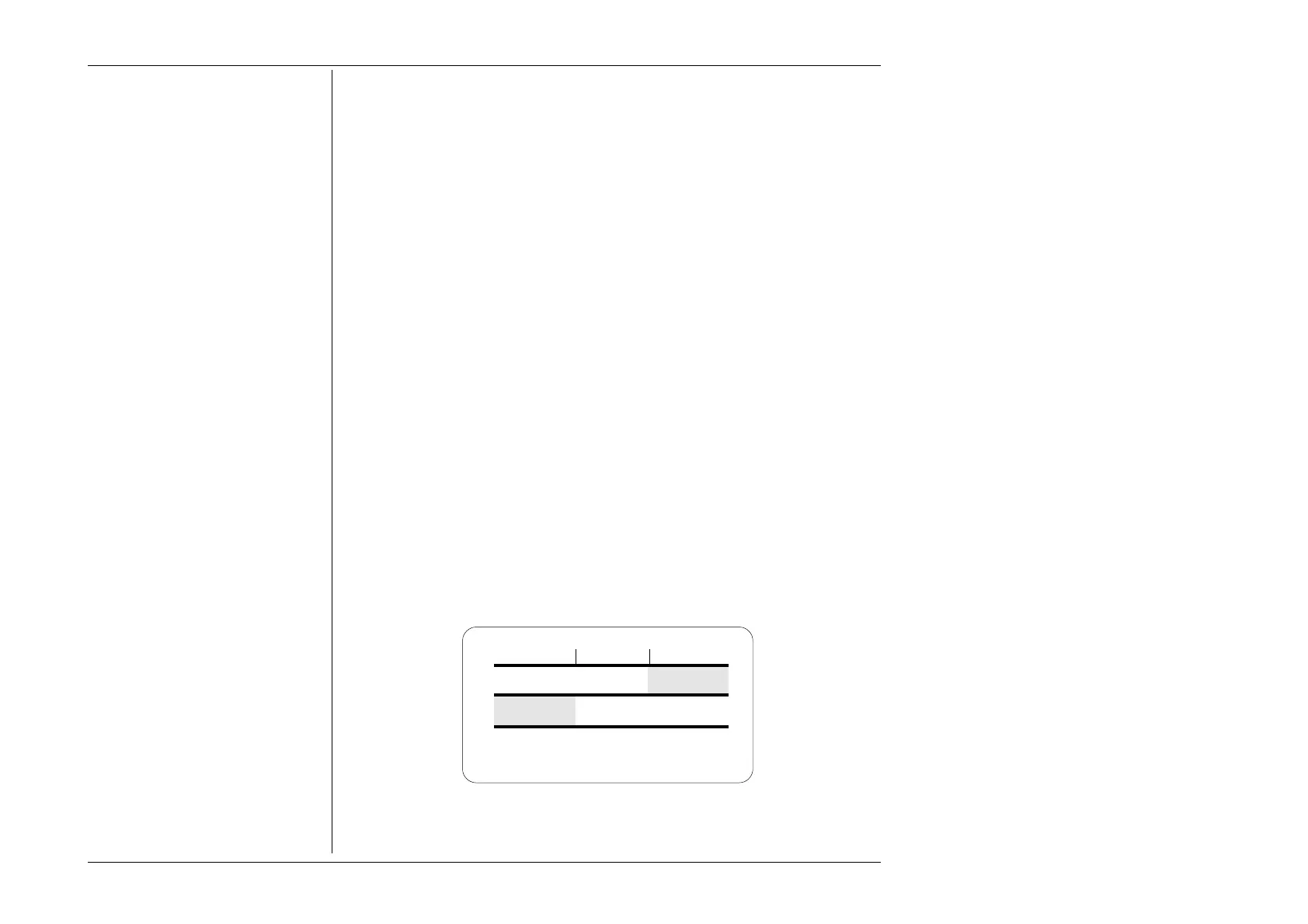
Each threshold value is related to the value set on the screen, including any Deviation. The
default state boundaries are shown in Fig. 4.4.1. The values given in the figure translate
to DC volts in DCV function, and RMS volts in ACV function.
Low Voltage State →
← High Voltage State
100V90V
Fig. 4.4.1 Default Settings of
ACV Low and High Voltage States
Comtinued Overleaf
→