4.5-14 Section 4: Using the Model 9100: DC Current Function
Final Width = 215mm
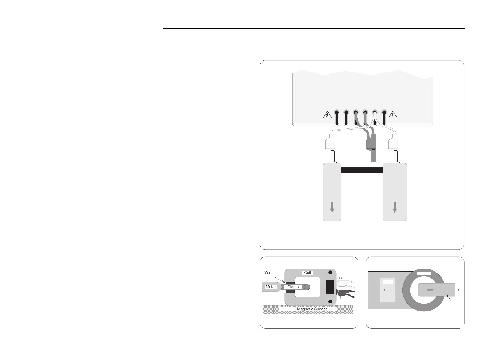
4.5.7 DC Current Routines for Calibrating UUTs (Contd.)
4.5.7.1 Interconnections (Contd.)
I+mAI+ 20ALI-
sLsHH
WhiYellBlkBlkRedRed
Work Mat
I+ 20A lead
in position to
energise the
10-Turn coil
I+ 20A lead
in position to
energise the
50-Turn coil
50-Turn
coil
10-Turn
coil
LI- lead
connects to
the required
coil Common
socket
Fig. 4.5.4 Interconnections for DC High Current UUT Calibration
Using the 10-Turn or 50-Turn Current Coils
Notes about positioning the current
sensing clamp in the center air space
of the coils:
The two coils on the assembly have been
optimally designed to reduce the effects of
stray magnetic fields at the pick-up position
for sensor clamps. The design gives
characteristics which would normally be
associated with central air spaces of much
larger area, more closely simulating single-
conductor pick-ups.
However, there are several types of clamp
meter; some having different requirements
for placing the clamp around the pick-up
conductor. Manufacturers normally give
instructions for aligning the clamp or meter
with respect to the conductor. When the
meter is clamped to any conductor, errors
may arise whose magnitude is similar to
the uncertainty of the meter if precautions
are not observed, so the manufacturer's
instructions should be strictly followed
when using the 9100 to calibrate the clamp
meter.
To obtain consistent results, in the absence
of manufacturer's instructions, the following
guidelines should be observed:
• Fig 4.5.5. With the coils located on a
non-magnetic surface (not the work
mat, as it has a steel core), place the
clamp in position so that it surrounds
the vertical arm of the coil. Keep the
clamp mid-way up the vertical arm,
and away from the corners.
• Fig 4.5.6. Place the vertical arm of the
coil, as far as is possible, in the center
of the air space of the clamp. Align the
center axis of the meter along the plane
of the coil itself.
• During later normal measurements
using the clamp meter, place the clamp
in the same position with respect to the
pick-up conductor as it was when being
calibrated.
Fig. 4.5.6 Position of CoilFig. 4.5.5 Position of Clamp
Meter
Clamp
Top of Coil
Plane of Coil
Vertical
Arm
AAAAAAAAAAAAAAAAAAAAAAAAAAAAAAAAAAAAAAAAAAAAAAAAAAAAAA
A
AAAAAAAAAAAAAAAAAAAAAAAAAAAAAAAAAAAAAAAAAAAAAAAAAAAA
AAAAAAAAAAAAAAAAAAAAAAAAAAAAAAAAAAAAAAAAAAAAAAAAAAAA
AAAAAAAAAAAAAAAAAAAAAAAAAAAAAAAAAAAAAAAAAAAAAAAAAAAA
A
AAAAAAAAAAAAAAAAAAAAAAAAAAAAAAAAAAAAAAAAAAAAAAAAAAAAAA
Non-Magnetic Surface
Coil
ClampMeter
I+
I-
 Loading...


