4.7-8 Section 4: Using the Model 9100: Resistance Function
Final Width = 215mm
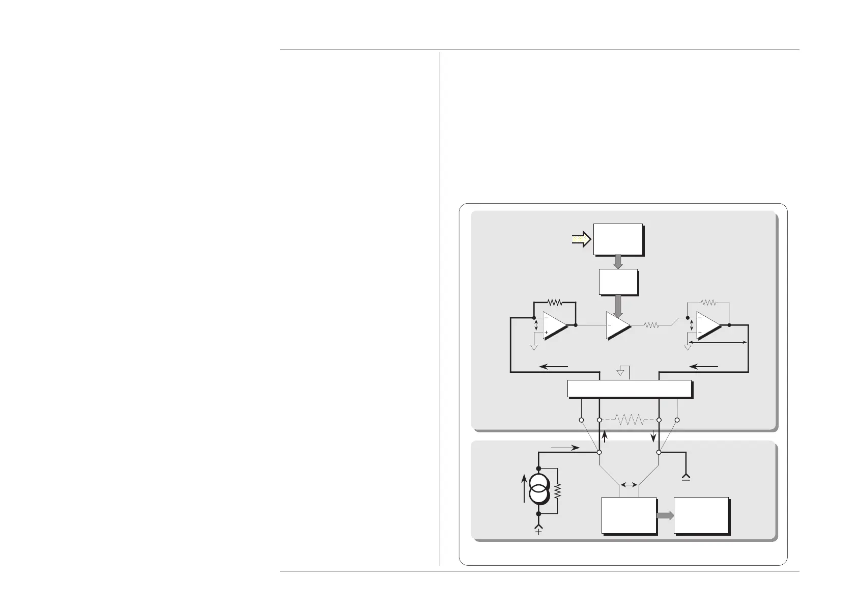
4.7.5.4 Configuration for Resistance Function in the 9100
The 9100 uses 'Active Impedance' technology to output a 'Virtual Resistance'. The
method relies on the UUT having a form of measurement illustrated by Fig. 4.7.1.
The 9100 will produce a DC voltage (
V
R
) in response to a DC current (I
R
) being sourced
from the UUT. The value of the voltage is derived electronically from the value of the
I
R
multiplied by the Total Resistance Demand value (R
T
) set on the display (including the
variation due to offset and deviation settings): V
R
= I
R
x R
T
.
The effect is that of placing a resistor of value
R
T
(Virtual Resistance) between the front
panel Hi and Lo terminals of the 9100. The method is shown in Fig. 4.7.2.
Fig. 4.7.2 Model 9100 Configuration for Resistance Function
I
R
Hi Lo
Model 9100
Virtual R
T
Gain
Control
Total
Resistance
Demand
G
R
IN
R
SET
R
STD
0V 0V
I
R
V
R
Lead-Impedance Compensation Bridge
Voltage
Measurement
Resistance
Calculation
and Display
Pseudo
Constant
Current
Source
V
R
Ω
Com
Sense Hi Sense Lo
I
R
UUT
 Loading...


