Section 4: Using the Model 9100: Conductance Function 4.8-7
Final Width = 215mm
4.8.5.2 Hardware Configurations
When increasing or decreasing output conductance, using any method: if the new
conductance is too large or small for the present hardware configuration, then if OUTPUT
is OFF there will be no noticeable effect as the hardware reconfigures.
If OUTPUT is ON, the new hardware will be reconfigured as quickly as possible to
minimize the disturbance to autoranging UUTs.
4.8.5.3 Configuration for Conductance Measurement in UUTs
Instruments which measure conductance generally use a method which drives a 'pseudo-
constant' current (I
G
) through the test circuit (usually a resistor) and measures the voltage
(V
G
) developed across it. Internal circuits then calculate the conductance digitally, using
the Law:
Conductance: G = I/V
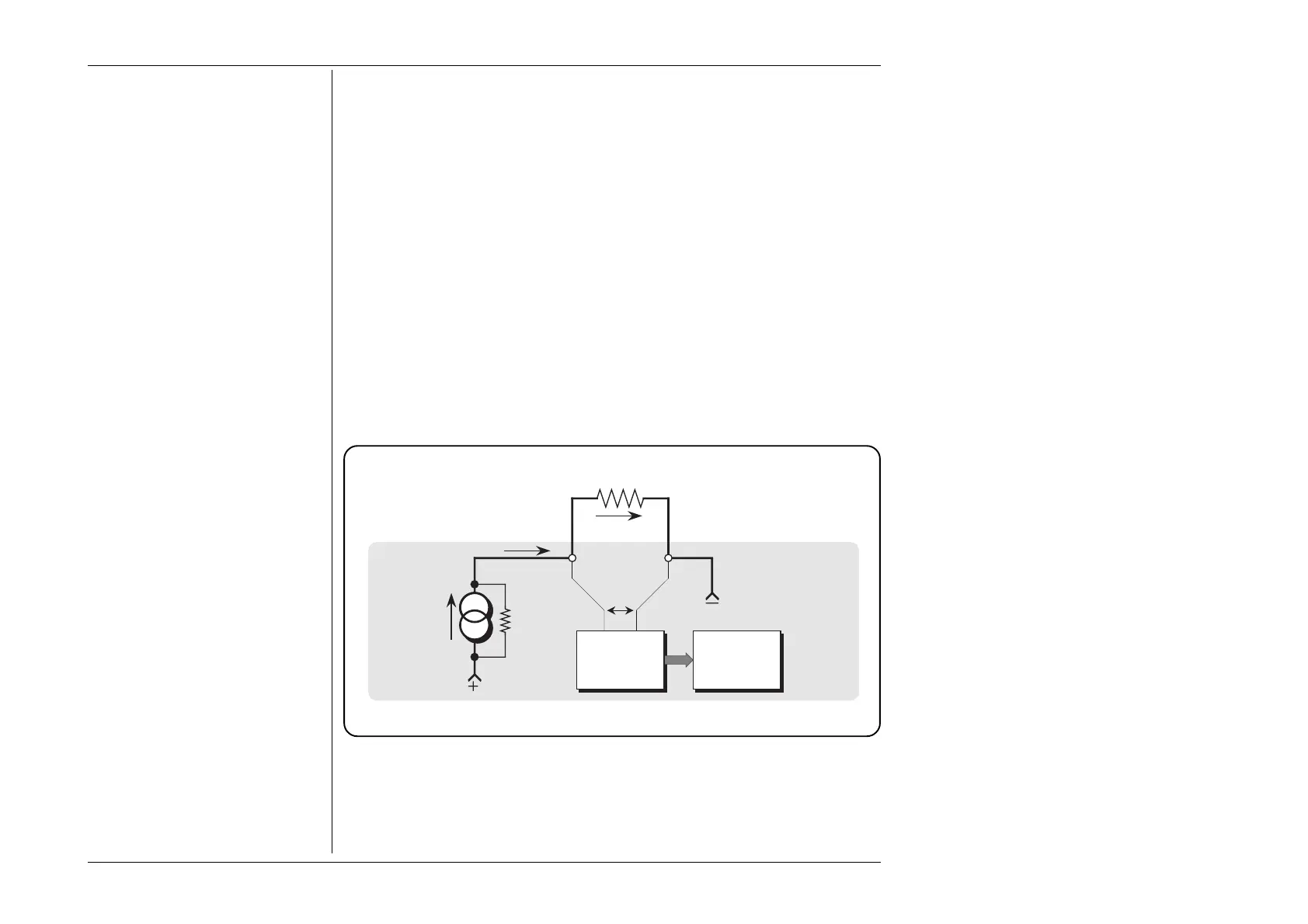
The 9100 assumes that this form of measurement is employed by the UUT. A simplified
illustration is shown in Fig. 4.8.1:
Note that because the current passes through external leads connecting the test conductance
to the terminals, the voltage sensed across the terminals will include the lead volts drops,
so the conductance result here will be reduced slightly due to the lead resistance.
Fig. 4.8.1 UUT Configuration for Conductance Measurement
Test
Conductance
I
G
Voltage
Measurement
Conductance
Calculation
and Display
Pseudo
Constant
Current
Source
V
G
Ω
Com
UUT