4.13-8 Section 4: Using the Model 9100: Capacitance Function
Final Width = 215mm
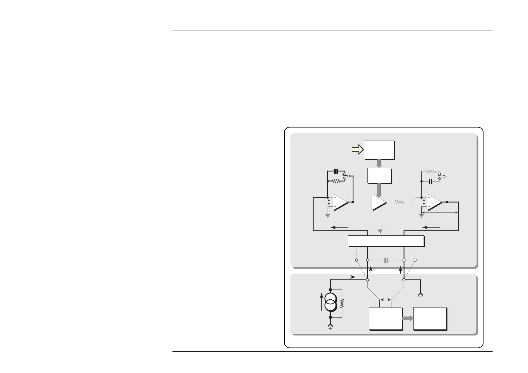
4.13.5.4 Configuration for Capacitance Function in the 9100
The 9100 uses 'Active Impedance' technology to output a 'Virtual Capacitance'. The
method relies on the UUT having a form of measurement illustrated by Fig. 4.13.1.
The 9100 will produce a voltage (V
C
) in response to a stimulus current (I
C
) being sourced
from the UUT. The instantaneous voltage value (v
c
) is derived from the instantaneous
value of stimulus current (i
c
) modified by the Total Capacitance Demand (C
T
) set on the
9100 display (including any Offset and Deviation variations): dv
c
/dt = i
c
/C
T
.
The effect is that of placing a virtual capacitance of value (C
T
) between the front panel
Hi and Lo terminals of the 9100. The method is shown in Fig. 4.13.2, below:
Fig. 4.13.2 9100 Configuration for Capacitance Function
Model 9100
UUT
Hi Lo
Virtual C
T
Lead-Impedance Compensation Bridge
Voltage
Measurement
Capacitance
Calculation
and Display
Pseudo
Constant
Current
Source
V
C
Ω
Com
Sense Hi Sense Lo
I
C
I
c
Gain
Control
Total
Capacitance
Demand
G
C
IN
R
SET
C
STD
0V 0V
I
c
V
c
A
B
A
B
R
STD
R
IN