4.13-12 Section 4: Using the Model 9100: Capacitance Function
Final Width = 215mm
4.13.6 Capacitance Routines for Calibrating UUTs
4.13.6.1 Interconnections
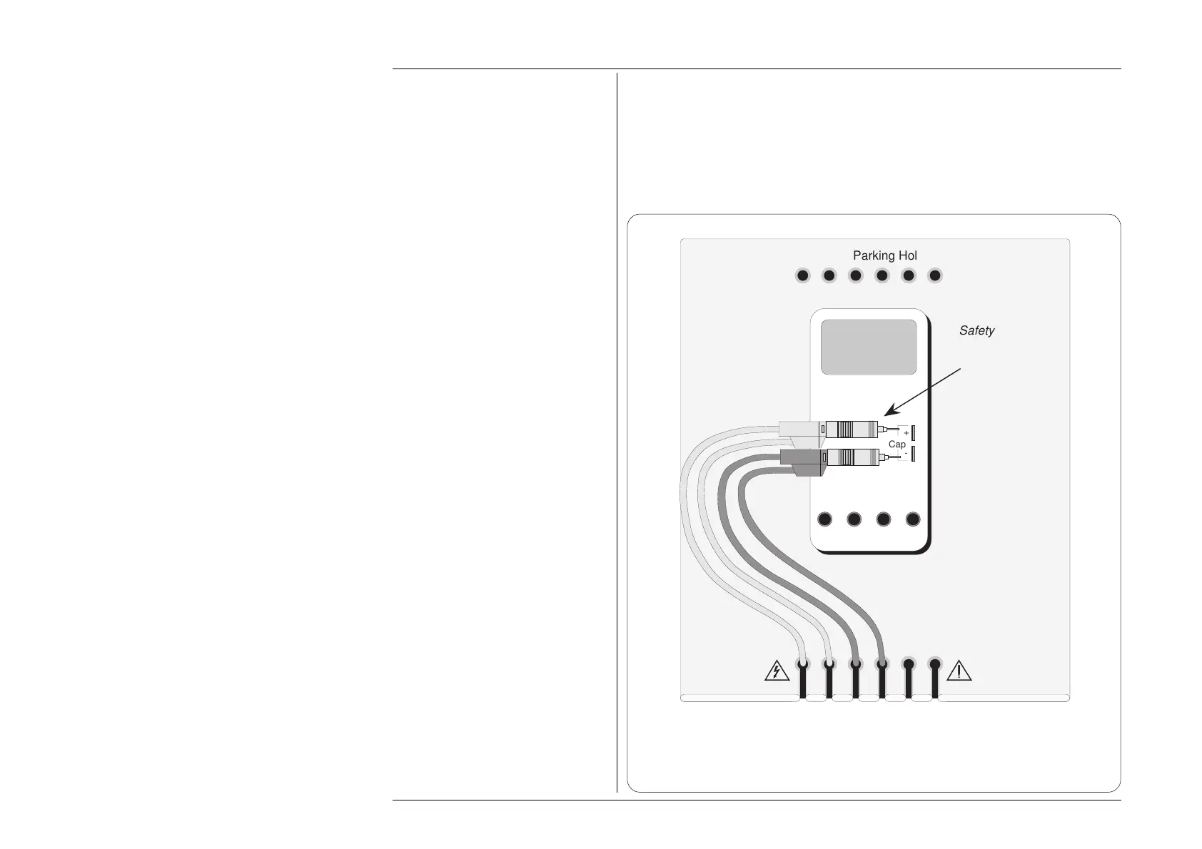
The general connection scheme for UUT calibration is illustrated in Fig. 4.13.4.
For UUTs without safety banana sockets, use appropriate adaptors.
Do not twist the leads together — separate them as far as possible.
Fig. 4.13.4
Interconnections for 4-Wire or 2-Wire Capacitance UUT Calibration
(Leads which are not shown are not connected)
10A mA COM V-
Cap
+
-
K-type
+
-
Safety Bananas
Terminated with
Probe Adaptors.
For those UUTs on
which one of the
capacitance terminals
is marked with a '+'
sign, always observe
the correct polarity as
shown. If no terminal
is marked '+', try
reversing the
connections, and then
use the least-noisy
arrangement.
Some UUTs use
standard safety
banana sockets for
Capacitance
measurement. In
these cases the
adaptors will not be
required
Adaptor Parking Holes
Work Mat
UUT
I+mAI+ 20ALI-
sLsHH
WhiYellBlkBlkRedRed