Section 4: Using the Model 9100: RTD Temperature Function 4.15-11
Final Width = 215mm
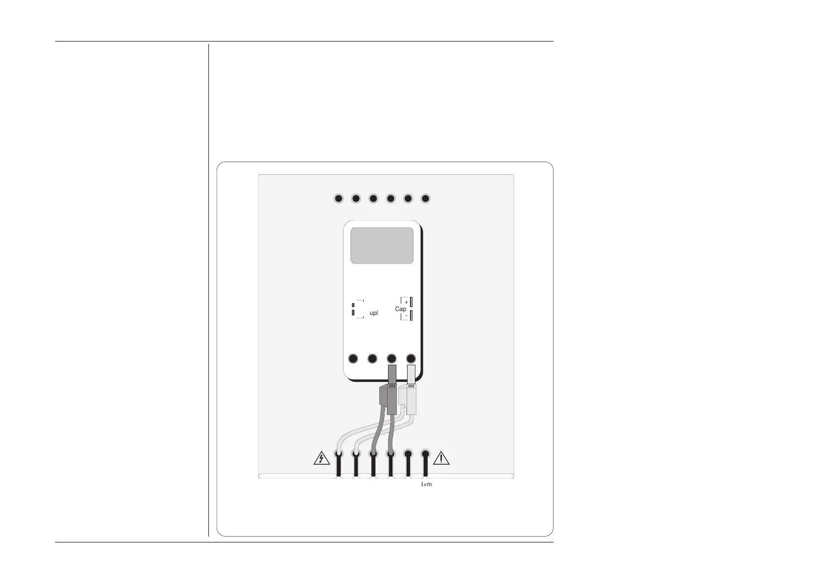
Fig. 4.15.4 Interconnections for UUT RTD Temperature Calibration
(Leads which are not shown are not connected)
4.15.7 RTD Temperature Routines for Calibrating UUTs
4.15.7.1 Interconnections
The general connection scheme for UUT calibration is illustrated in Fig. 4.15.4. The use
of either 4-wire remote sensing at the UUT terminals, or 2-wire local sensing at the 9100
terminals, is served by the same connections from the 9105 at the work mat. Selection
of 2/4-wire is carried out on the 9100 front panel.
For UUTs without safety banana sockets, use appropriate adaptors.
10A mA COM V-
Cap
+
-
I+mAI+ 20ALI-
sLsHH
WhiYellBlkBlkRedRed
Adaptor Parking Holes
Work Mat
UUT
Thermo
Couple
+
-