4.18-10 Section 4: Using the Model 9100: Insulation/Continuity Function (Option 135)
To perform a verification of an insulation tester, the following procedure should be
followed:
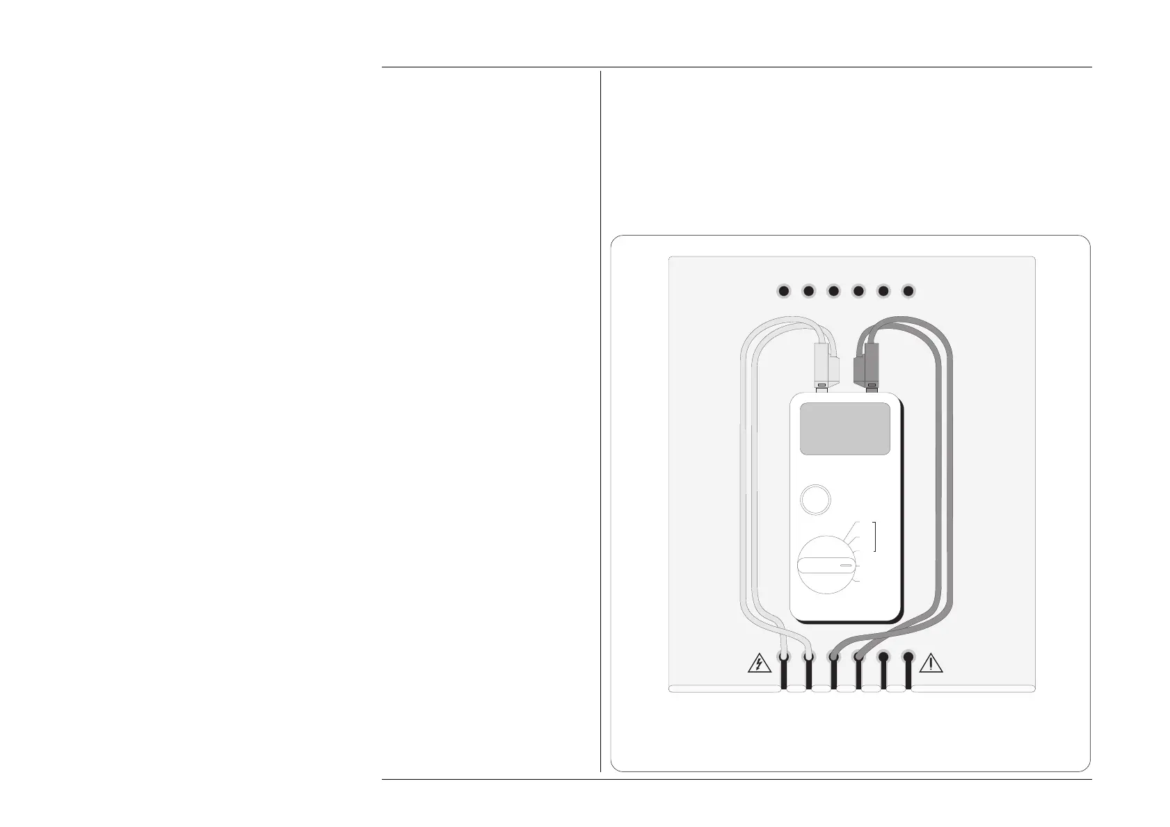
1. Connect the insulation tester’s positive output terminal to the 9100 HI terminal and
the insulation tester’s negative output terminal to the 9100 LO terminal. You may
connect the UUT either in 2-wire or 4-wire configuration, as the high-voltage active
impedance is a 2-wire function. Assuming the UUT has 4mm input terminals, it is
recommended that you use the 9105 leadset. See the diagram below:
Fig. 4.18.1
Interconnections for Insulation Tester Calibration
(UUT may need to be oriented differently to connect leads. Leads not shown are not connected)
I+mAI+ 20ALI-
sLsHH
WhiYellBlkBlkRedRed
Adaptor Parking Holes
Work Mat
UUT
TEST
1kV
500V
250V
OFF
Continuity
Insulation
+–