4.19-8 Section 4: Using the Model 9100: DC Power Function - Operation
Final Width = 215mm
4.19.5 Crossing Thresholds
4.19.5.1 DC Power Resolution Thresholds
The different resolutions are distinguished by two characteristics:
Maximum and minimum values available.
Absolute resolution of the least-significant digit.
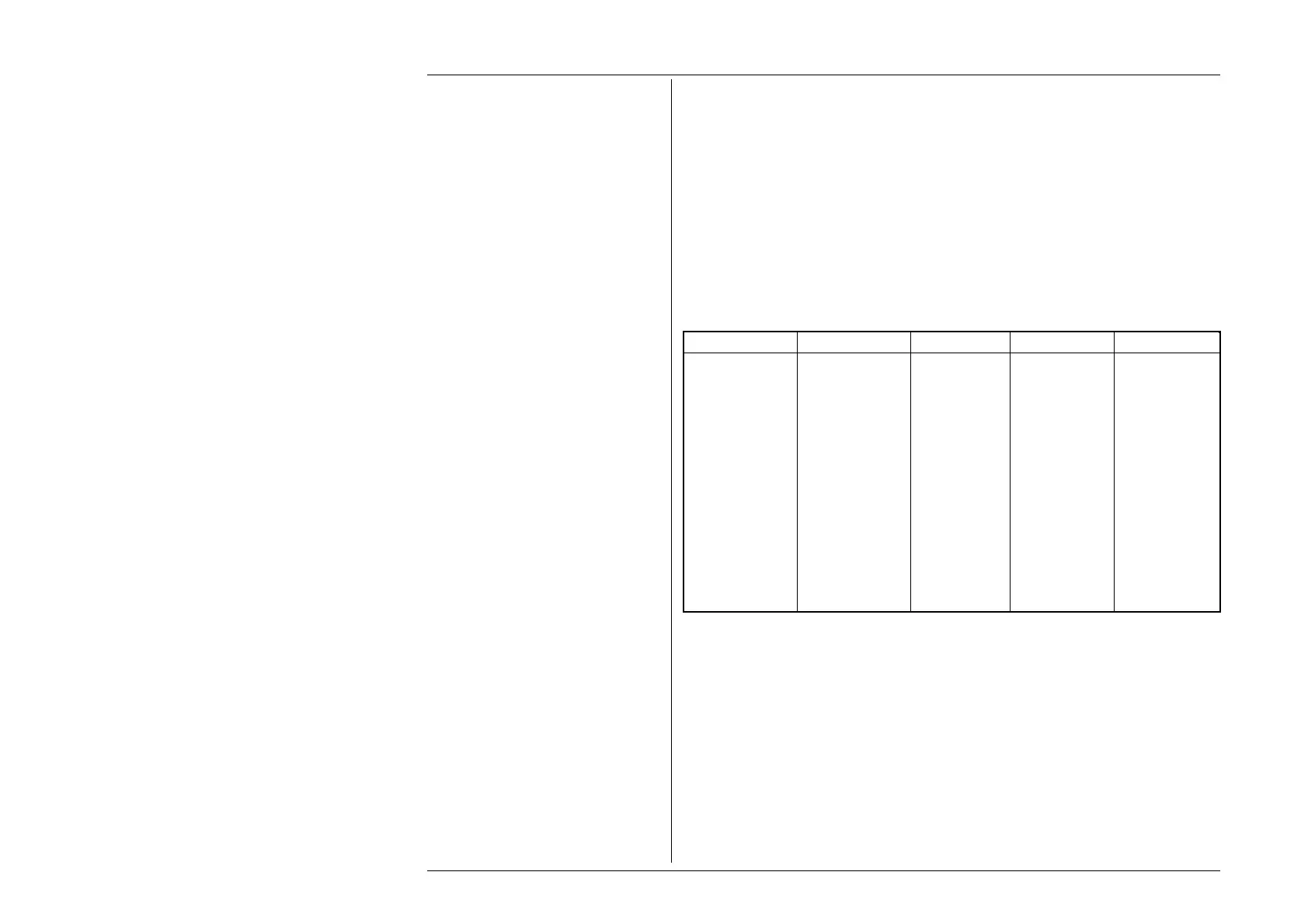
The following table shows the spans of output values in the DC Power function, against
the associated resolutions:
Default Display Ranges ('Power =' Field):
Min Value Max Value Sig. Figures Dec. Places Legend
00.0000 32.0000 6 4 µW
000.000 320.000 6 3 µW
0.00000 3.20000 6 5 mW
00.0000 32.0000 6 4 mW
000.000 320.000 6 3 mW
0.00000 3.20000 6 5 W
00.0000 32.0000 6 4 W
000.000 320.000 6 3 W
0.00000 3.20000 6 5 kW
00.0000 32.0000 6 4 kW
000.000 320.000 6 3 kW
0.00000 3.20000 6 5 MW
00.0000 07.8750 6 4 MW
When Aux volts is configured as current at non-default scaling factors, the above field is extended..
Rules, built into firmware, govern passage across thresholds between resolutions: These rules are generally the same as
described in Section 4.4.5.1.
Best available resolution and specification are obtained immediately using direct entry.