4.20-12 Section 4: Using the Model 9100: AC Power Function - Operation
Final Width = 215mm
4.20.5 Crossing Thresholds
4.20.5.1 AC Power Resolution Thresholds
The different resolutions are distinguished by two characteristics:
Maximum and minimum values available.
Absolute resolution of the least-significant digit.
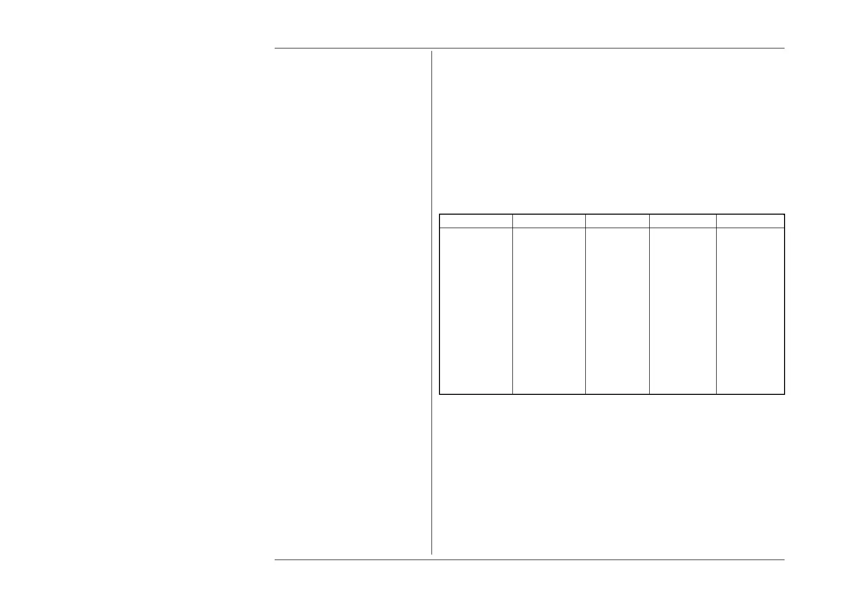
The following table shows the spans of output values in the AC Power function, for
‘sinusoidal’ waveshape only, against the associated resolutions:
Default Display Ranges ('P =' Field):
Min Value Max Value Sig. Figures Dec. Places Legend
00.0000 32.0000 6 4 µW or µVA
000.000 320.000 6 3 µW or µVA
0.00000 3.20000 6 5 mW or mVA
00.0000 32.0000 6 4 mW or mVA
000.000 320.000 6 3 mW or mVA
0.00000 3.20000 6 5 W or VA
00.0000 32.0000 6 4 W or VA
000.000 320.000 6 3 W or VA
0.00000 3.20000 6 5 kW or kVA
00.0000 32.0000 6 4 kW or kVA
000.000 320.000 6 3 kW or kVA
0.00000 3.20000 6 5 MW or MVA
00.0000 07.8750 6 4 MW or MVA
When Aux volts is configured as current at non-default scaling factors, the above field is extended..
Rules, built into firmware, govern passage across thresholds between resolutions: These rules are generally the same as
described in Section 4.4.5.1.
Best available resolution and specification are obtained immediately using direct entry.
If direct entry into the Power field is used, Current and Phase must first be set to suitable values.
For information concerning other waveshapes and available voltages, refer to Sections 7.4 and 7.6.