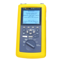
DSP-4000 Series
Users Manual
2-22
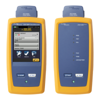
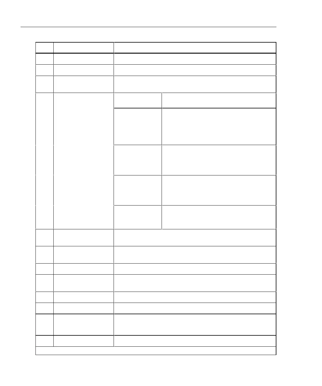
Table 2-5. Remote Connectors and Features
Item Feature Description
1
RS-232C serial port A DB9P connector for loading software updates.
2
2.5 mm phone jack Connection for the headset supplied with the test tool.
3
AC adapter/
charger jack
Connection for the ac adapter/charger supplied with the test
tool.
LED off,
unit turned off
Battery is not charging.
The charger is not plugged in.
LED off,
unit turned on
Battery is not charging.
The charger is not plugged in or the test
tool is running a test. When the test is
finished, charging resumes unless the
battery is already charged (>80%).
LED flashing
red
Fast charge pending.
Charging is beginning. This state may last
for several minutes until fast charging
begins.
LED steady red Fast charge.
The unit stays in fast charge mode for up to
4 hours, or until either the battery is fully
charged or a test is initiated.
4
AC power indicator
LED steady
green
Charge complete.
Fast charge is complete. The unit enters
trickle charge mode.
5
LIA connector and
latch
Connector and latch for attaching link interface adapters.
6
Pass LED A green LED that turns on at the end of a test if no faults were
detected.
7
Test LED A yellow LED that turns on when a test is in progress.
8
Fail LED A red LED that turns on at the end of a test if one or more faults
were detected.
9
Talking LED A LED that turns on when the Talk mode is active.
0
Low-battery LED A LED that turns on when the remote battery voltage is low.
f
X
TALK
Lets you use the headset for two-way voice communication
over twisted pair or fiber cable. When the Talk mode is active,
this button controls the headset volume.
g
Rotary switch On/off switch for remote.
The LEDs, items 6-10, also briefly indicates the battery charge level when you turn on the remote.