FS-ST8
Digital Proportional Radio Control System
16
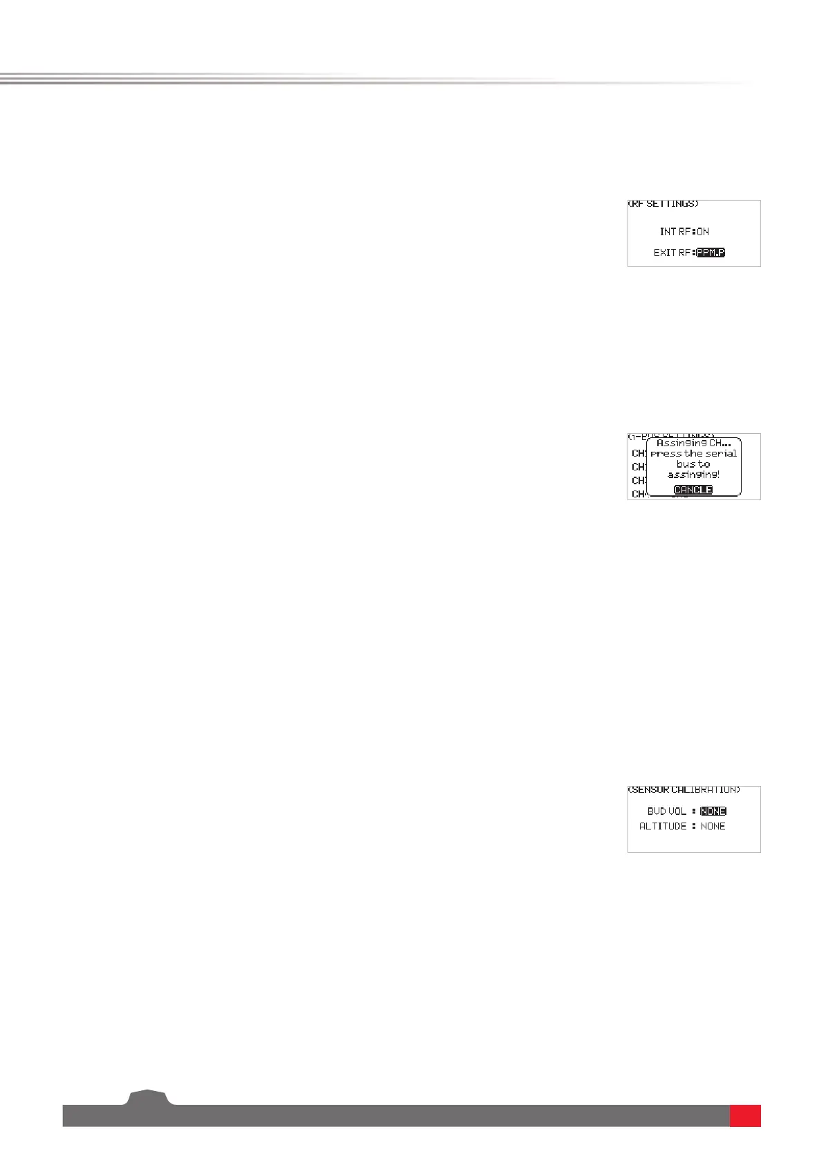
This is an extended function option. The setting is used when the external RF module is needed.
This function is a unique and powerful serial communication protocol system provided by FLYSKY. It can be output
to any channel by setting. For receivers with i-BUS interface and corresponding accessories, such as Serial Bus
Receiver FS-CEV04. This function will be displayed when you set the OUTPUT to i-BUS mode via BIND SETTINGS
function.
6.2.4 RX SET - RF SETTINGS
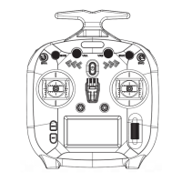
6.2.5 RX SET - i-BUS SETTINGS
Function settings:
1. SelectRF SETTINGS andpressScroll Wheel toenter.
2. Selecta item you want to set usingScroll Wheel.
3. SelectanappropriateitemandpressScroll Wheel to conrm. PressEXITto
saveandexit.
Function settings:
1. The transmitter FS-ST8 and the receiver FS-SR8 are bound successfully.
Connect the input cable of the Serial Bus Receiver FS-CEV04 to the SERVO
interface of the receiver.
2. At the transmitter side, select i-BUS SETTINGS andpressScroll Wheel to
enter.
3. Select a channel to be assigned,thesystemwillshowapromptmenu,if the
channel is incorrect, select CANCEL to cancel.
4. If the selected channel is about to assign to C1 channel of the Serial Bus
Receiver FS-CEV04, then press the button K1 corresponding to C1 channel
of FS-CEV04 receiver by a long thin tool. After the setting is successful, the
system will pop up a menu showing successful.
Note: If the receiver is overloaded, please supply power separately to prevent the wire from
being burnt out due to excessive current.
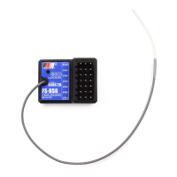
This function is a special feature provided by FLYSKY. The setting allows you to make corrections to the parameters
of some external sensors that need to be calibrated, so as to display the sensing data accurately. For example, for
the external voltage sensor (BVD), after calibration, the displayed data will be closer to the real value.
This function needs to be used with the GPS sensor of FLYSKY. You can view the information returned by GPS sensor
after calibrating the GPS and setting an appropriate time. You can reset the start point when the displayed distance
is inaccurate.
6.2.6 RX SET - SENSOR CALIBRATION
6.2.7 RX SET - GPS SETTING
Function settings:
1. SelectSENSOR CALIBRATION andpressScroll Wheel toenter.
2. Selecta item you want to set usingScroll Wheel.
3. SelectanappropriatevalueandpressScroll Wheel to conrm. PressEXITto
saveandexit.
GPS DISPLAYTodisplaytheinformationreturnedbyGPSsensor.
GPS CALIBRATIONTocalibratetheheightvalue.
TIME ZONETosetanapproriatetimezone.Aftersetting,youcanviewthedate
andtimeviaGPSDISPLAY.