FS-ST8
Digital Proportional Radio Control System
2
[28]
[29]
[27]
[26]
[25]
2.Introduction
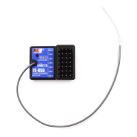
This product uses the 2.4 GHz ANT (Ant Protocol) automatic frequency hopping digital system, consisting of FS-
ST8 transmitter and FS-SR8 receiver. It has an output of 8-10channels, compatible with model xed-wing aircraft,
delta-wing airplanes, helicopters, gliders, multicopters, engineering vehicles, robots, etc.
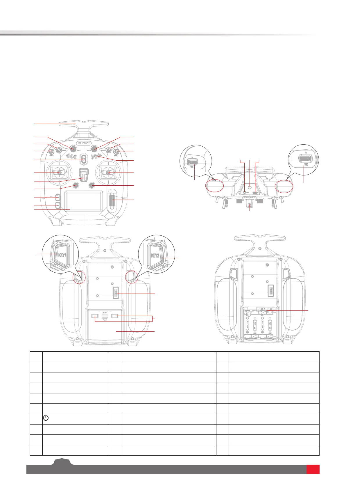
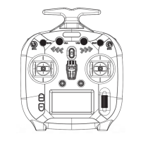
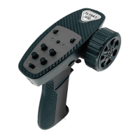
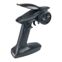
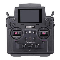
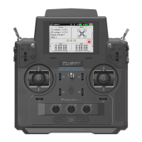
2.1 Transmitter overview
[1]
[2]
[3]
[4]
[5]
[6]
[7]
[8]
[9]
[10]
[18]
[16]
[15]
[17]
[14]
[13]
[12]
[11]
[30]
[20]
[21]
[19]
[22]
[23]
[24]
[1]
Display
[11]
Carrying Handle
[21]
Trainer Jack(3.5mm audio head)
[2]
EXIT Button
[12]
VRB Knob
[22]
A Reserved Hole for SMA Antenna
[3]
MENU Button
[13]
SWC Three-position Switch
[23]
Type-C Port
[4]
T1/T2 Trim Button
[14]
SWD Two-position Switch
[24]
VRD Knob(For upgraded version)
[5]
Neck Strap Hook
[15]
LED Indicator
[25]
KEY1 Button(For upgraded version)
[6]
Left Stick
[16]
Right Stick
[26]
KEY2 Button(For upgraded version)
[7]
(Power Switch)
[17]
T3/T4 Trim Button
[27]
Stealth I/O RF module interface
[8]
SWA Two-position Switch
[18]
Scroll Wheel
[28]
A Reserved Hole for XT30 Cable)
[9]
SWB Two-position Switch
[19]
A Hole for Fixing the Cell Phone Holder
[29]
Battery Compartment
[10]
VRA Knob
[20]
VRC Knob(For upgraded version)
[30]
JST Jack