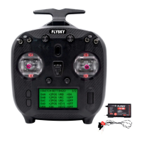
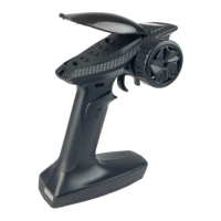
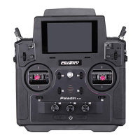
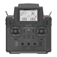
FS-ST8
Digital Proportional Radio Control System
4
Light on in red: The receiver is connected to the power supply. It works normally.
Fast ashing: The receiver is in the bind mode.
Slow ashing: The LED ashes slowly when the receiver is powered o, unbound, or no signal.
Three-ash-one-o: The rmware of the receiver is upgrading.
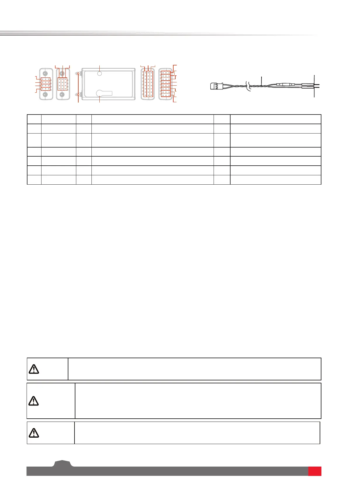
2.2.2 Interface
All the interfaces are 2.54 mm standard pins for connecting the receiver to each terminal part of the model. Please
follow the direction according to the direction on the the receiver.
2.3 Antenna
Attention
• To ensure the signal quality, the transmitter and receiver antennas should be
kept vertical to the ground as much as possible. In operations, please adjust the
transmitter angle. Make the antenna towards the direction of the model receiver.
Keep the receiver antenna extending out of the model and perpendicular to the
ground.
Warning
• It is strictly prohibited to hold the antenna of the transmitter and the antenna of the
receiver in operations. Otherwise, the quality and strength of the radio transmission
signal will be greatly reduced, resulting in the failure and out of control of the model.
Attention
• Do not pull the antenna of the receiver. Do not tie the antenna and the servo cable
together. Do not put the antenna close to the metal materials, because this will aect
the signal strength of the receiver.
It should be noted that this is a transmitter with two built-in antennas. Please use the transmitter correctly.
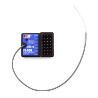
2.2 Receiver overview (FS-SR8)
The status LED indicates the power supply state of the receiver and its working state.
O: The receiver is not powered on.
[1]
[2]
[3]
[4]
[5]
[6]
[7]
[16]
[18][17]
[8]
[9]
[10]
[11]
[12]
[15][14][13] [13][14][15]
[19]
[20]
[21]
2.2.1 LED Status
[1] CH1/PPM [8] CH8 [15] Signal pin
[2] CH2 [9] BIND interface [16] LED
[3] CH3 [10] BVD/VCC(Battery voltage detection/
Power supply interface)
[17] Antennas
[4] CH4 [11] SENS interface [18] BIND button
[5] CH5 [12] SERVO/S.BUS interface [19] BVD harness
[6] CH6 [13] - (Power cathode) [20] Connect to battery positive pole
[7] CH7 [14] + (Power anode) [21] Connect to battery negative pole