25CI400A/W • 25HI400A • 50CI400A/W • 50HI400A 25
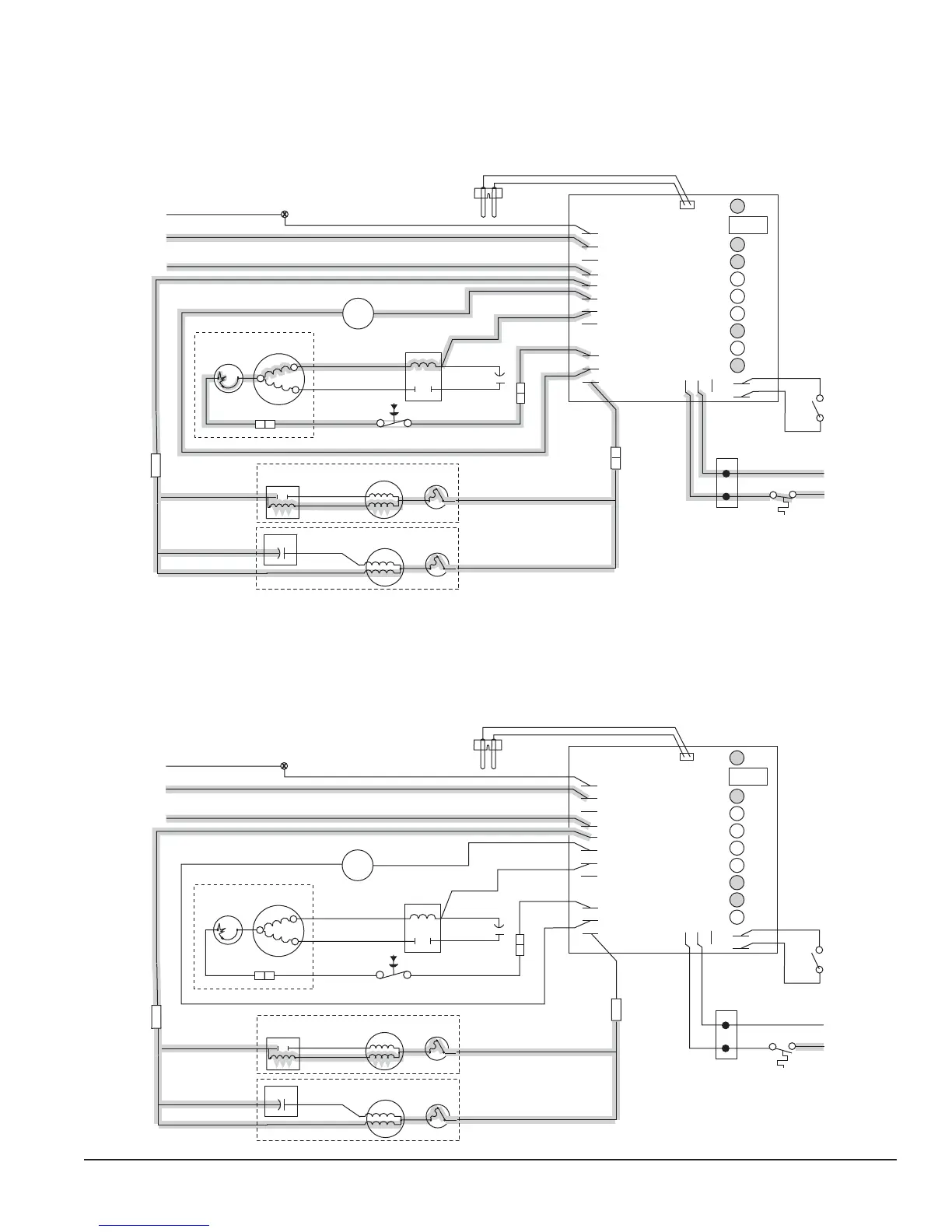
Normal operation – Stage 3
After the initial high current draw drops off, the gearmotor start relay contacts open, dropping out the start winding
(or start capacitor). As the compressor comes up to normal running speed, the compressor start relay contacts also
open, dropping out the start winding of the compressor. The ice machine is now in a normal icemaking mode. The ice
machine will begin to produce ice and continue to produce ice until the bin level control in the ice dispenser is satis ed.
The PWR, B-E, DR, C and WTR LEDs are all on.
GRD
L1
L1
L2
L2
L2
L2
L2
COMPRESSOR
FAN
DRIVE
DR
C
20M
60M
2ND
WTR
B-T
B-E
RESET
GRD
G
B
W
FAN
BLACK
WHITE
BLACK
BLACK
R
ORANGE
S
S
L
COMPRESSOR
C
RED
BLACK
BLACK
INPUT
POWER
WATER
SENSOR
CONTROL
BOARD
BLACK
24V
COMMON
LINE VAC
RED
RED
WHITE
BLACK
BIN T-STAT
BIN SIGNAL
FROM DISPENSER
JUNCTION BOX
(MCD400A/WVS series –
blk wire is on 24V)
WHITE
RED
WHITE
M
1
COMPRESSOR
SWITCH
PWR
BLACK
T.O.L.
BLACK
RED
HIGH PRESSURE
SAFETY SWITCH
M
WHITE
WHITE
BLUE
RELAY
START
T.O.L.
BLACK
4
2
3
YELLOW
GEAR MOTOR
T.O.L.
GEAR MOTOR
RED
START
RUN
RUN
START
START CAP.
BISON GEARMOTOR
LINIX GEARMOTOR
OR
Normal operation – Stage 4
Once the ice level control opens, the B-E LED goes out. After a 10 second delay the compressor LED (C), compressor
and fan motor go off. (Should the ice level control not remain open for 10 seconds, the ice machine will continue to
run.) The gearmotor continues to run and the DR LED remains lighted for 60 seconds. The purpose of this function is
to drive the remaining ice out of the evaporator and to boil off any refrigerant remaining in the evaporator. The bin timer
LED (BT) comes on, starting the twenty minute off cycle time delay.
GRD
L1
L1
L2
L2
L2
L2
L2
COMPRESSOR
FAN
DRIVE
DR
C
20M
60M
2ND
WTR
B-T
B-E
RESET
GRD
G
B
W
FAN
BLACK
WHITE
BLACK
BLACK
R
ORANGE
S
S
L
COMPRESSOR
C
RED
BLACK
BLACK
INPUT
POWER
WATER
SENSOR
CONTROL
BOARD
24V
COMMON
LINE VAC
RED
RED
WHITE
BLACK
BIN T-STAT
BIN SIGNAL
FROM DISPENSER
JUNCTION BOX
(MCD400A/WVS series –
blk wire is on 24V)
WHITE
RED
WHITE
M
1
COMPRESSOR
SWITCH
PWR
BLACK
T.O.L.
BLACK
RED
HIGH PRESSURE
SAFETY SWITCH
M
BLACK
WHITE
WHITE
BLUE
RELAY
START
T.O.L.
BLACK
4
2
3
YELLOW
GEAR MOTOR
T.O.L.
GEAR MOTOR
RED
START
RUN
RUN
START
START CAP.
BISON GEARMOTOR
LINIX GEARMOTOR
OR