18 25CI400A/W • 25HI400A • 50CI400A/W • 50HI400A
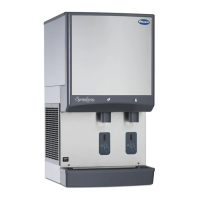
Fig. 24 – Water-cooled only
24.2
24.1
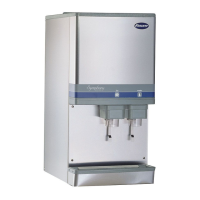
13. Use hooks on ice machine electrical box to hang
box on bracket (Fig. 24.1).
14. Remove ice machine from dispenser (Fig. 24.2).
Fig. 25 – All models
T
OP
• Electrical box must be in “UP” position
before supplying power
• Start relay is gravity sensitive, and MUST
be in “UP” position
• Failure to comply may cause equipment
to overheat, resulting in equipment failure,
equipment damage or fire hazard
!
WARNING
icemaker
electrical box
TOP
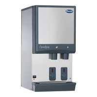
Evaporator disassembly
Note: The upper bearing, lower bearing and auger
assemblies must be replaced as assemblies. The bottom
and top bearing assemblies cannot be eld assembled to
factory speci cations (Fig. 26).
1. Disconnect power to ice machine.
2. Shut off water to ice machine.
3. Drain evaporator and oat tank.
4. Disconnect plastic tubing from evaporator water
inlet.
5. Disconnect compression nozzle tubing and reservoir
over ow tubing from secured clip.
6. Remove nut and upper vee-band coupling from top
of evaporator.
7. Lift top bearing assembly straight up with a slight
rotating motion and remove.
8. Remove ice compression loop located at top
ofauger.
9. Lift auger straight up and out of evaporator.
10. Remove nut and lower vee-band coupling from
bottom of evaporator.
11. Lift evaporator to clear bottom bearing assembly.
12. Loosen hex head bolt in side of mounting base with
5/16" wrench and lift lower bearing assembly.
13. Remove condensate shield.
14. Remove four Allen head machine screws holding
mounting base to gearbox.
15. If replacing evaporator, remove compression nozzle
from evaporator port.
Fig. 26