25CI400A/W • 25HI400A • 50CI400A/W • 50HI400A 7
12. Raise the dispenser upright and position in desired
location.
13. Mark dispenser outline on counter and remove
dispenser.
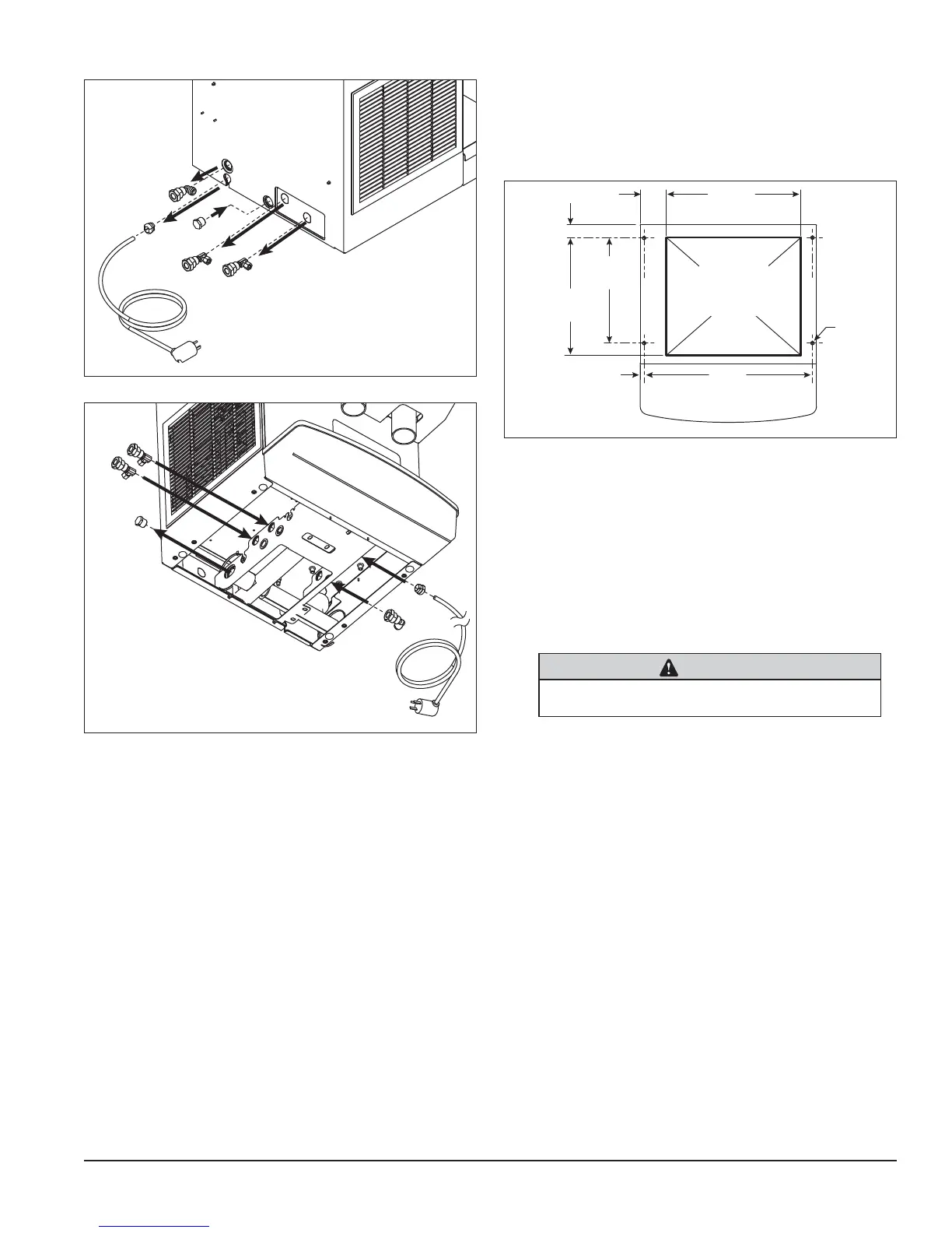
Fig. 6
Countertop cutout viewed from top
16.00"
(40.7 cm)
3.13"
(80 mm)
12.50"
(31.8 cm)
1.56"
(40 mm)
14"
(35.6 cm)
20"
(50.8 cm)
.50"
(13 mm)
4X
Ø.375"
(10 mm)
hole
Cutout
connections
through
bottom
14. Cut countertop utility opening and drill four 7/16"
holes to anchor dispenser to counter (Fig. 6).
15. Apply a thick bead approximately 1/4" (7 mm)
diameter of NSF listed silicone sealant (Dow
Corning* RTV-732 or equivalent) 1/4" (7 mm) inside
marked outline of dispenser.
16. Reposition dispenser on counter and secure to
counter with four 3/8"-16NCbolts.
17. Smooth excess sealant around outside of dispenser.
18. Make utility connections through countertop cutout.
CAUTION
• Do not connect water-cooled condenser outlet line to
the dispenser drain line.
19. Turn on water supply and check for leaks.
20. Clean and sanitize dispenser and ice machine
before putting into service.
21. Turn power on and allow ice machine to produce
ice.
Fig. 4
4.1
4.2
4.3
4.4
Fig. 5
5.1
5.2
5.3
5.4
2. Disconnect the internal water line from the potable
water connection tting.
3. Remove tting from the back wall of the dispenser
(Fig. 4.1).
4. Relocate tting to internal bulkhead and reconnect
(Fig. 5.1).
6. Remove power cord strain relief (Fig. 4.2).
7. Relocate the cord and strain relief to the internal
bulkhead and reconnect (Fig. 5.2).
8. Water-cooled only. Disconnect internal condenser
water inlet and outlet ttings (Fig. 4.3).
9. Water-cooled only. Relocate water inlet and outlet
ttings and reconnect (Fig. 5.3). Note: The water
inlet is connected to the condenser; the outlet line is
connected to the water regulating valve.
10. Remove the drain plug from the internal drain line
connection point (Fig. 5.4).
11. Relocate to back of dispenser and reconnect
(Fig.4.4).