Process Flow Rate 4-20mA Analog Output
The 4-20mA output of the FT3 HART represents the process ow rate measurement, linearized and
scaled according to the congured range of the instrument. This output corresponds to the Primary
Variable. HART Communication is supported on this loop.
Channel 2 of the 4-20mA output may be congured for ow or temperature values when using HART.
HART Indicators
Green LED indicator LP3 cycles on and o to indicate that the FT3 is operating. Orange LED indicator
LP2 blinks when HART signals are received and Yellow LP1 blinks when HART signals are transmitted.
The LEDs are located on the HART communication board next to the wiring connections.
The orange LED indicator LP2 will be on continuously when HART communication is enabled and the
4-20mA wiring is not connected.
FT3 HART Communication Setup
HART communication must be selected in the FT3 Serial Communication menu for HART
communication to operate. When this communication parameter is changed, power to the FT3 must
be cycled for it to take eect.
HART Parameters
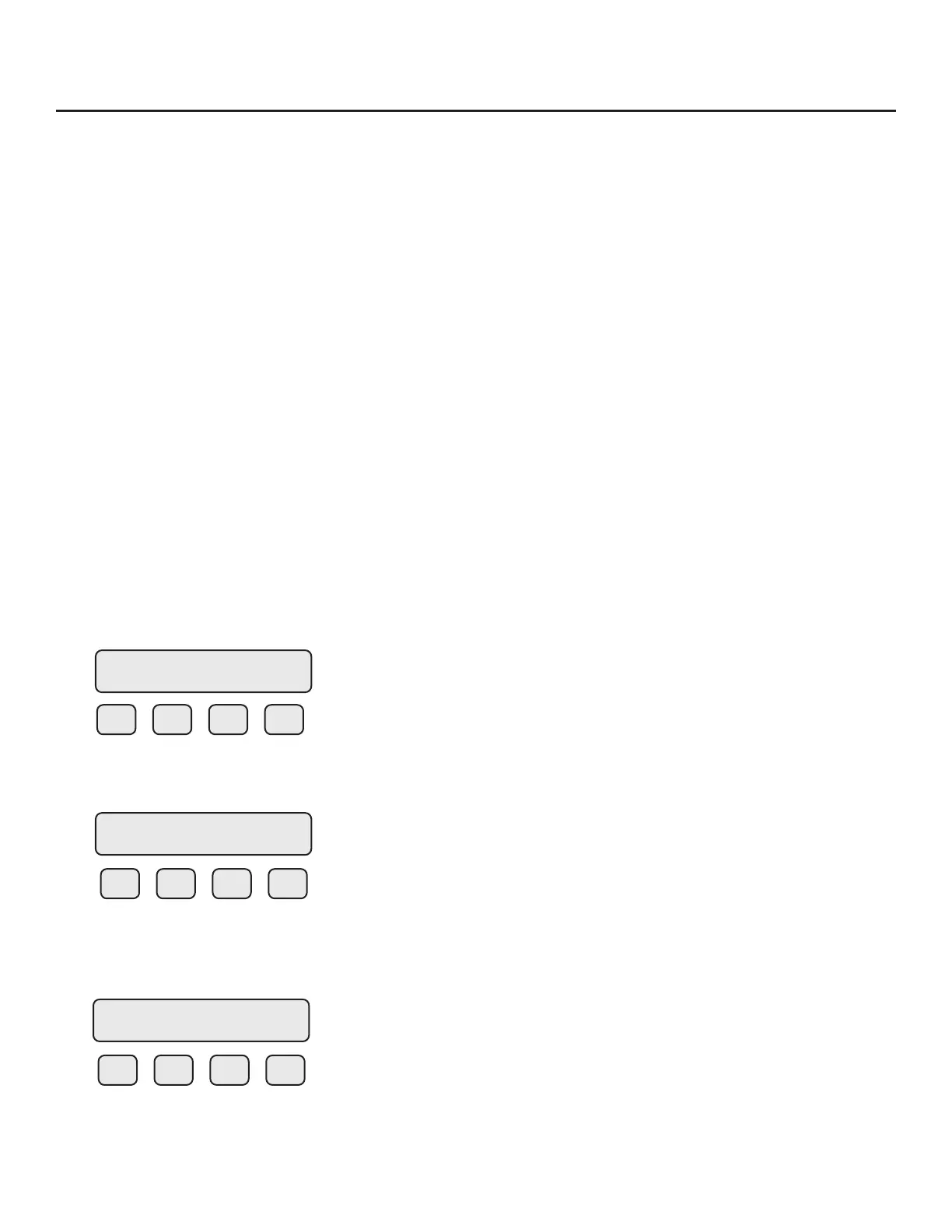
To program the communication parameters, press I/O (F1) key from the SET PARAMETERS menu.
F1 F2 F3 F4
Choose I/O (F1) to access the communication output.
F1 F2 F3 F4
Then press COM (F1) to select communication parameters.
Set Bus protocol for HART:
F1 F2 F3 F4
Press NXT (F1) until HART is selected as shown and then press OK (F4) to accept the setting.
SET PARAMETERS
I/O FLO DSP EXIT
SET I/O
COM PUL 420 EXIT
Comm=HART
NXT OK
Communications | 102
Model FT3
Communications