9. Carefully slide the probe out of the retractor along with the tting while supporting the meter as
it comes out. Be careful while handling the meter so the sensor does not get damaged.
How to Insert the Probe into the Flow Stream (Valve closed, System Pressurized)
WARNING! Never stand where your body or any part of it is in front of the meter. An injury
may occur if the probe is forced outward by the system pressure.
1. Apply a thin lm of anti-seize compound on the compression tting threads, if needed.
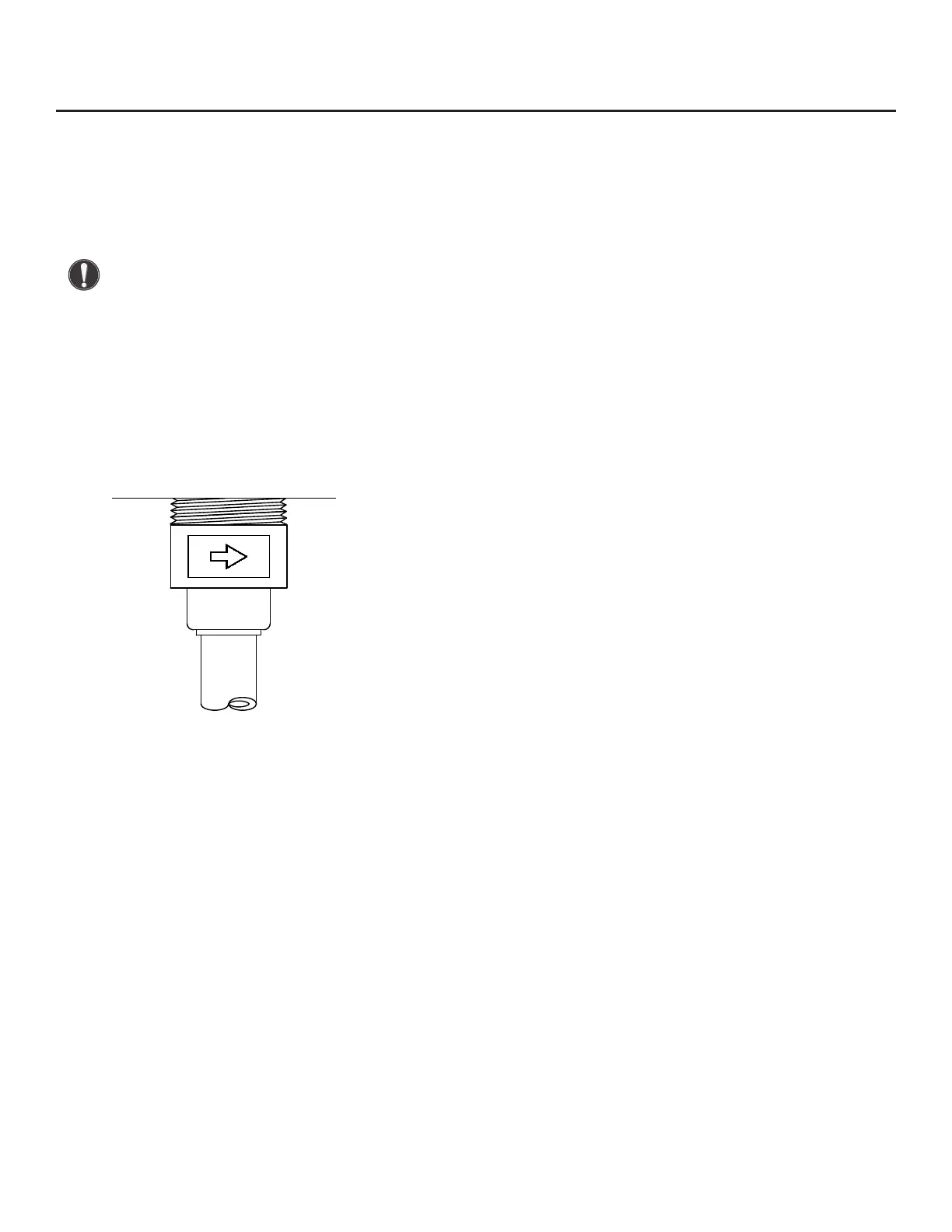
2. Push the probe into the retractor and tighten the compression nut by hand. Align the probe with
the ow by rotating the probe until the ow direction arrow on the probe tting is aligned with
the centerline of the pipe, and points in the direction of ow (see Fig. 7.3).
Fig. 7.3: Flow Direction Arrow
3. Tighten the compression nut onto the compression tting using a 7/8” wrench on the nut and a
7/8” wrench on the tting.
4. Pressurize the system and check the retractor for leaks. Tighten any of the ttings that may need
it or seal any leaks that require it.
5. The system may be wired at this point. Refer to the wiring section of this manual for wiring
instructions for the electronics enclosure. Power may be applied only after the meter has been
properly wired according to the manual, and it is safe to do so.
Maintenance | 115
Model FT3
Maintenance