F1 F2
F3 F4
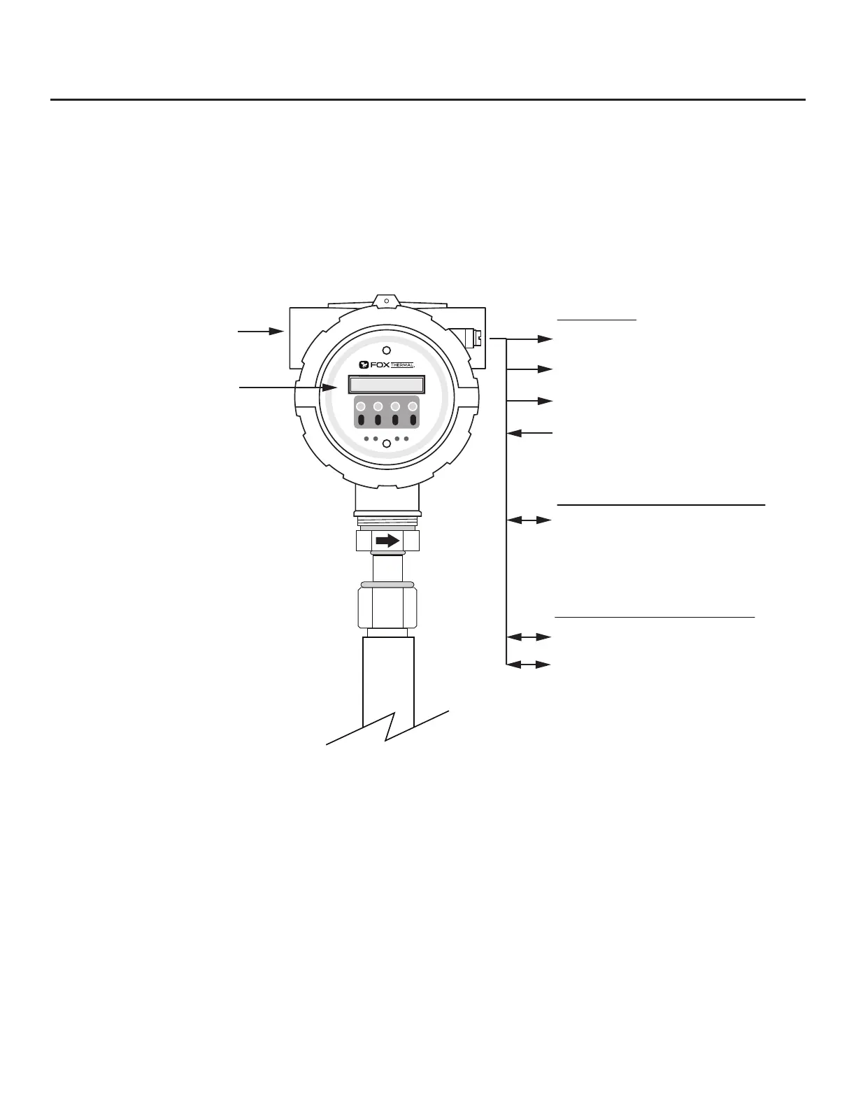
Standard I/O
4-20mA Flow
Contact Input
4-20mA Flow or Temperature
Pulse or Alarm Output
USB
(Free FT3 View™ Software)
Outputs and Communications are Galvanically Isolated
Optional Serial Communications
HART
Modbus RTU (RS485)
24VDC Input Power
100-240VAC Optional
Optional Display and
Configuration Panel
Standard Digital Communications
FT3 Functional Diagram
An on-board 2 line x 16 character backlit LCD display shows ow rate, total ow, elapsed time, process
gas temperature, and alarms. The display is also used in conjunction with the Conguration Panel for
eld conguration of ow meter settings such as 4-20mA scaling, pulse output scaling, pipe area, zero
ow cuto, ow ltering or damping, display congurations, diagnostics, and alarm limits.
Fig. 1.11: FT3 Function Diagram
Model FT3
Introduction | 19
Introduction