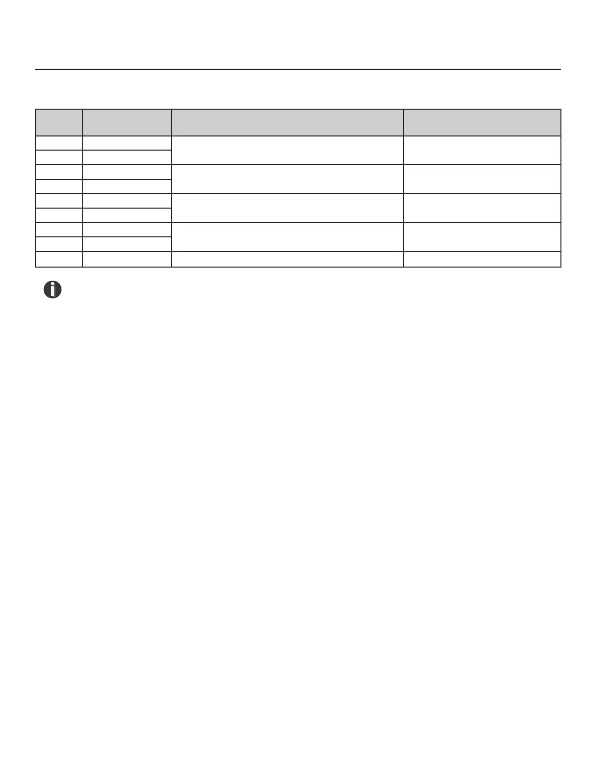
Table 5.1: FT3 Modbus Holding (cont'd)
Communications | 93
Model FT3
Communications
Modbus
Register
Data Type Description Units
40061 32-bit oat LSW Zero Check Pipe Ref Zero Check Pipe Reference
40062 32-bit oat MSW
40063 32-bit oat LSW Zero Check Pipe Di Zero Check Pipe Dierence %
40064 32-bit oat MSW
40065 32-bit oat LSW Zero Check Bottle Ref Zero Check Bottle Reference
40066 32-bit oat MSW
40067 32-bit oat LSW Zero Check Bottle Di Zero Check Bottle Dierence %
40068 32-bit oat MSW
40069 16-bit int Zero Check Test Time Zero Check Test Time (seconds)
NOTES!
• In the table, LSW means Least Signicant Word, and MSW means Most Signicant Word.
In this case a “word” is one 16-bit Modbus register. A 32-bit oat or 32-bit integer is
stored in a pair of Modbus registers. When a register is designated as “32-bit int LSW”, it
means that bits 0-15 of the variable are in that register. A register designated as MSW has
bits 16-31 of the variable. For instance, the ow total can be read as a 32-bit integer from
registers 40003 (LSW) and 40004 (MSW). If the ow total is 0x12345678, then register
40003 will hold 0x5678, and register 40004 will hold 0x1234.
• 32-bit oating point values are dened by the IEEE 754 standard: https://ieeexplore.ieee.
org/document/8766229
• Refer also to Wikipedia: https://en.wikipedia.org/wiki/Single-precision_oating-point_
format
Example:
Request data register at starting address 0x0000 and specifying only 1 register:
<0x01> <0x03> <0x00> <0x00> <0x00> <0x01> <0x0a> <0x84>
Command Response
<0x01> <0x03> <0x02> <xx> <xx> <CRC high> <CRC low>
Where xx is the data register value.