VYPER
™
VARIABLE SPEED DRIVE
INSTALLATION - OPERATION - MAINTENANCE
100-210 IOM (JUL 09)
Page 16
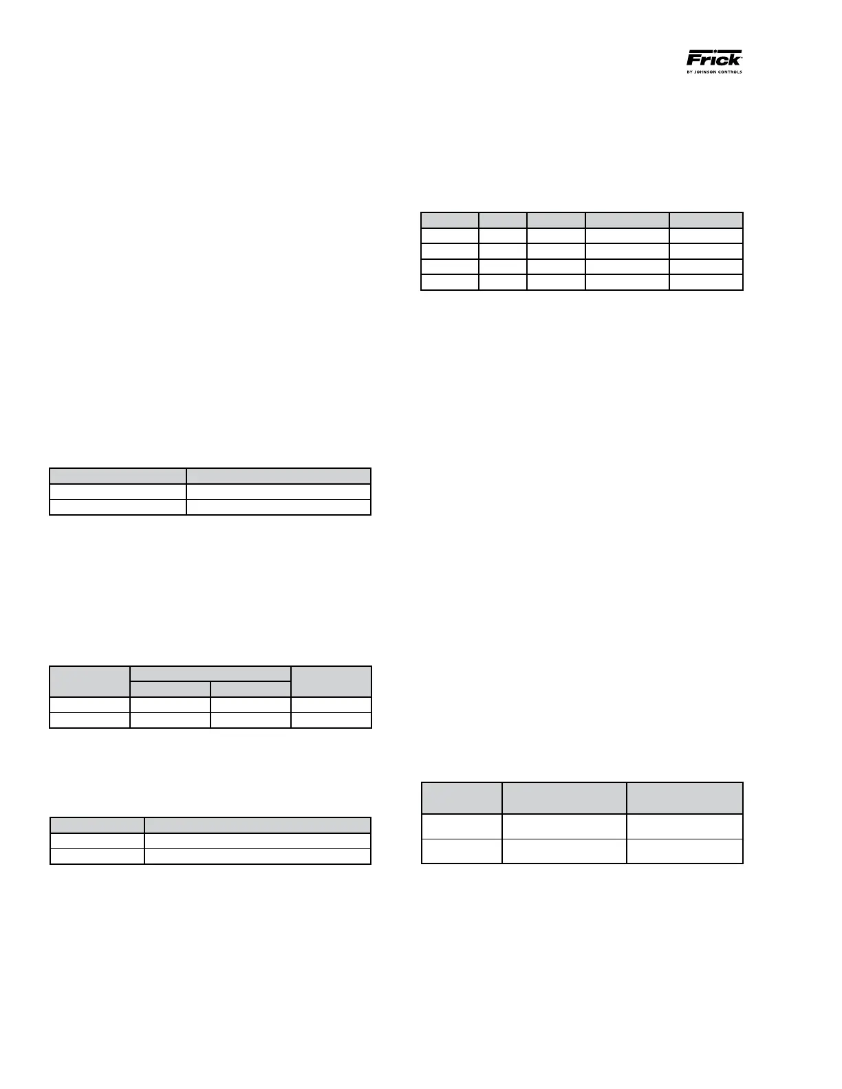
CURRENT LIMITS
The drive is capable of outputting the rated full load current
over the operating frequency range of the drive. The unit is
started with the compressor fully unloaded until the frequency
reaches the minimum operating frequency range. In addition,
the drive is capable of operating without a load for ease of
service. Refer to Table 4 for current limits.
The following information is also helpful in the operation of
the unit:
• Overload:105%offullloadratingforseven(7)seconds.
• Efciency:98%Typicalatratedloadandfrequency.
INPUT SHORT CIRCUIT LIMITS
Vyper
™
drives are suitable for use on circuits capable of
delivering up to 100,000 RMS symmetrical amperes and a
maximum of 480 VAC.
The Vyper
™
can be affected by specific events that can de-
crease product life and cause component damage related to
the input power conditioning. These events include:
• Thepowersourceexperiencesinterruptions.
• The power system has power factor correction
capacitors switched in and out of the system by either
the power supplier or the end user.
• Thepowersourcecontainsvoltagespikeswhichcould
be caused by equipment on the same line or natural
phenomena such as electrical storms.
If one or more of these conditions exist, Frick recommends
that the end user install minimum impedance between the
Vyper
™
and the power source. A transformer or other similar
device can supply the impedance.
A 100% rated input power circuit breaker with ground fault
protection and external lockable operator is supplied as
standard. The circuit breaker is sized in accordance with the
National Electrical Code or UL requirements. Refer to Table
5 for circuit breaker ratings and lug sizes.
Horsepower
Circuit Breaker
Rating (Amps)
Circuit Breaker
Lug Sizes
700/572 1000 3/0 to 500 KCMIL
912/752 1200 3/0 to 500 KCMIL
Table 5 – Circuit Breaker Ratings and Lug Sizes
The maximum per phase Total Harmonic Distortion (THD)
of the input current shall not exceed 30% at 100% rated
power. The Frick
®
Vyper
™
drive typically produces between
20-30% THD.
An IEEE 519 Harmonic Filter is required if the THD of the input
current at the installation cannot exceed 8%. The IEEE 519
Harmonic Filter is highly recommended for crucial applications
such as hospitals, computer networks, airports, etc.
GENERAL OPERATION DESCRIPTION
The Vyper
™
serves as the motor starter and capacity control
for a Frick screw compressor. The Vyper
™
controls capacity by
reducing compressor speed and optimizing the compressor
efficiency at all loads.
The Vyper
™
varies the screw compressor speed by control-
ling the frequency and voltage of electrical power supplied
to the compressor motor. Unlike general purpose variable
speed drive units, the Vyper
™
is factory calibrated for maxi-
mum performance with Frick screw compressors. Because
of the specific application to commercial building systems,
the Vyper
™
has been designed to be electronically compat-
ible with other electronic equipment that typically operates
in the same facility.
The Vyper
™
can be cooled by two coolants: water or glycol.
Both coolants can be used with either package mounted or
remotely mounted Vyper
™
units. Power wiring and some pip-
ing between the facility and Vyper
™
must be field supplied.
ELECTRICAL LIMITS
Supply voltage to the Vyper
™
must be 440/460/480V @ 60
Hz or 380V @ 50 Hz. If a building has higher or lower sup-
ply voltage, consider a step-up or step-down transformer.
Refer to Table 1.
Extreme operating voltage ranges from a minimum of 414
VAC to a maximum of 508 VAC, 3-phase, 60 Hz, or 342 to
423 VAC, 50 Hz. The maximum allowable voltage imbal-
ance is 3%. Size the main transformer so voltage does not
sag more than 5% when subjected to load excursions. The
steady-state operating voltage should be within the range of
414 to 508 VAC, 3 phase, 60 Hz, or 342 to 423 VAC, 3 phase,
50 Hz. Refer to Table 2.
Unit controls may shut down with power interruptions up to
one cycle. Interruptions greater than one cycle will result in
a shutdown. A voltage dip below 391V, 60 Hz or 340V, 50 Hz
constitutes a power interruption. Refer to Table 3.
Frequency Supply Voltages VAC
60 Hz 440/460/480
50 Hz 380
Table 1 – Supply Voltage Requirements
Frequency
Operating Voltage Limits
Phase
Min Max
60 Hz 414 508 3
50 Hz 342 423 3
Table 2 – Operating Voltage Limits
Frequency Minimum Voltage Limits VAC
60 Hz 391
50 Hz 340
Table 3 – Power Interruption Minimum Voltage Limits
HP Freq Voltage RMS current LRA max
912 HP 60 Hz 460V 1180A 7014A
752 HP 50 Hz 400V 1180A 8205A
700 HP 60 Hz 460V 880A 5777A
572 HP 50 Hz 400V 880A 5780A
Table 4 – Unit Current Limits