VYPER
™
VARIABLE SPEED DRIVE
INSTALLATION
100-210 IOM (JUL 09)
Page 17
Installation
RIGGING AND HANDLING
Each Vyper
™
Variable Speed Drive unit is shipped mounted
on a wooden skid or mounted to the refrigeration package. All
shipping materials must be removed prior to unit installation.
The Vyper
™
cabinet unit is best moved via lifting lugs on the
top sides of the cabinet. Caution must be used to not damage
the pump or peripheral equipment on the rear of the cabinet.
Never move the unit by pushing against the Vyper
™
cabinet
with a forklift or other machinery.
UNIT (WITH FILTER) WEIGHTS (lb)
MODEL UNIT UNIT AS SHIPPED
700/572 1,890 2,319
912/752 2,026 2,455
VYPER
™
MOUNTING CONFIGURATIONS
NOTE: When mounting the Vyper
™
unit, allow space for
servicing both sides of the unit cabinet.
The Frick Vyper
™
is offered in two mounting configurations,
package mounted and remote mounted.
PACKAGE MOUNTED UNITS
One advantage of the package mounted version is that all
electrical connections have been prewired and tested at
the factory which ensures proper installation of control and
power lines. Package mounting is available for all horsepower
ratings of the Vyper
™
. Both water or glycol cooling connec-
tions are also available as well as the optional IEEE 519
harmonic filter. In addition, the package-mounted Vyper
™
does not require an additional dV/dt filter between the VFD
cabinet and the motor.
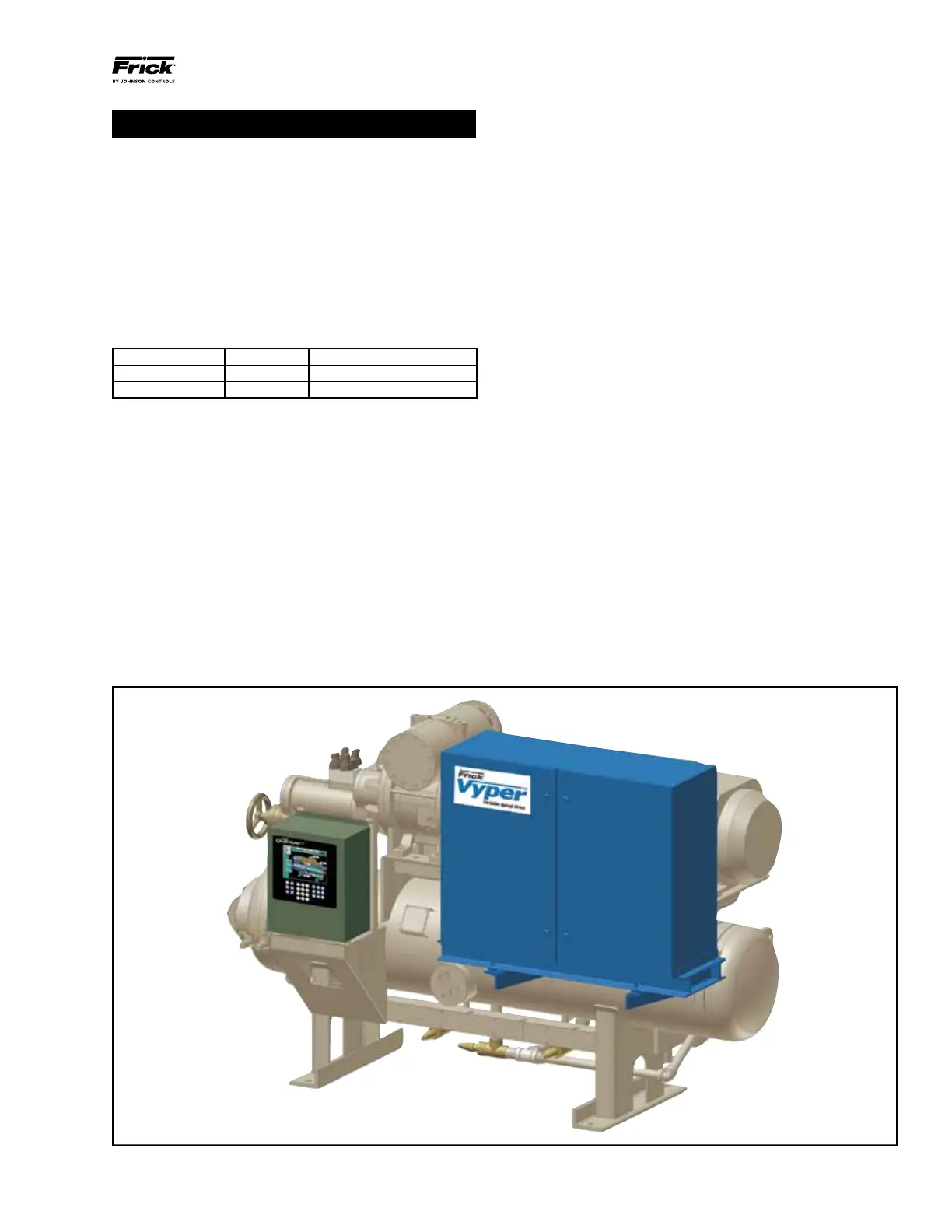
Figure 6 shows Vyper
™
cabinet mounted on a Frick RWF II
refrigeration package. Individual systems configurations will
vary according to model and horsepower sizes selected.
On package mounted units, the Vyper
™
cabinet is mounted
on a rectangular welded steel channel, which provides both
an attachment point for the cabinet’s side brackets and also
helps to maintain the rigidity of the cabinet during service.
The channel assembly / VSD cabinet is mounted on two
extension brackets welded to pads on the system’s oil separa-
tor. All package-mounted units are assembled with vibration
isolators located between the Vyper
™
channel frame and the
extension mounting brackets. The isolators help to minimize
the exposure of internal components and connections to
cyclic vibrations during unit shipping and operation.
Power supply to the Vyper
™
is from the top. Power supply to
the motor is made via a conduit exit from a rear panel in the
Vyper
™
Cabinet. Control wiring in/out is located at the lower
left side of the cabinet.
Please consult standard compressor package installation
procedures for this mounting method.
Drive Disconnect Height – covered under Exception 2,
section 8 of article 404 of the NEC, which states, Switches
and Circuit Breakers installed adjacent to motors, applianc-
es, or other equipment that they supply shall be permitted
to be located higher than 2.0 M (6 ft 7in) and to be acces-
sible by portable means.
Figure 6 - Vyper
™
Package Mounted on Frick RWF II. Diagram is for orientation purposes only and is not to scale.