VYPER
™
VARIABLE SPEED DRIVE
OPERATION
100-210 IOM (JUL 09)
Page 48
Capacity Control Setpoints
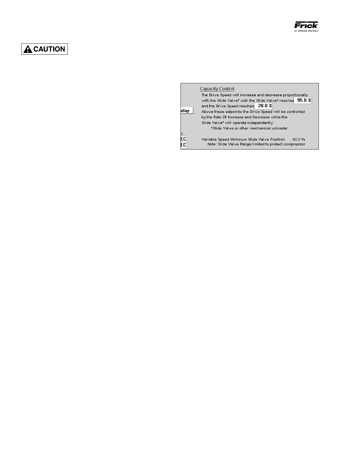
(See Figures 46 and 57)
The Capacity Control setpoints work directly in conjunction
with the VFD setpoints as the slide valve will be adjusted
according to the speed of the Vyper
™
Drive. The slide valve
rage of motion is limited by the Quantum
™
LX control panel.
Figure 57 - Motor Screen Capacity Control Setpoints
Programming the Capacity Control Setpoints - Program-
ming the Capacity Control Setpoints properly is critical to the
optimal performance of the Vyper
™
.
The operator must understand how the Motor Screen Capac-
ity Control parameters affect the functionality of the Vyper
™
unit. These setpoints affect the capacity of the unit by chang-
ing the position of the slide valve as well as the interaction
between the slide valve and motor speed.
Proportional Slide Valve Setpoint - This parameter sets
the maximum slide valve percentage at which the Vyper
™
operates under proportional capacity control in conjunction
with speed change. Proportional control exists between this
setpoint and the minimum slide valve position. This value
must always be set less than 100%.
Proportional Speed Setpoint - This setpoint represents the
maximum percentage of speed while under proportional con-
trol when used in conjunction with the slide valve. At speeds
higher than this setpoint, the capacity is under total speed con-
trol. At values between this setpoint and the minimum speed
setpoint, the compressor is under proportional control.
Minimum Slide Valve Position - This setting establishes the
minimum Slide Valve position possible while the Frick screw
compressor is running. At Minimum Drive Speed, this is the
point at which no further mechanical unloading is allowed.
This setpoint is programmed as a function of the chosen
minimum drive speed. This setpoint is adjustable to higher
minimum values but no lower than the default minimum. The
default minimum is dependent of the minimum speed/output
setpoint and is not user-programmable.The lower the mini-
mum output setpoint is, the higher the minimum Slide Valve
setpoint will be. When the minimum output is set to 20%, the
minimum Slide Valve will be set to 40%.
Programming the Minimum Drive
Ou tpu t S pee d
t o a se tpo in t
lower than the minimum speed
recommended by the compressor motor
may result in
severe damage to the
compressor motor.
Minimum Drive Output Speed - This parameter sets the
lowest allowable percentage of motor speed at which the
Vyper
™
will permit the motor to run for an indeterminate pe-
riod. The range on this function is 20 to 100%. The value of
this parameter must always be set lower than the Maximum
Percentage setting. The value of this setting is critical, as
many electric motors are not designed for low speed opera-
tion due to temperature and lubrication requirements. Frick
recommends that the manufacturer of the motor is contacted
to determine if the design can be safely operated at the
intended minimum speed.
Rate of Increase* - The Rate of Increase parameter setting
determines the speed change step size at which the Vyper
™
will accelerate the motor. The Rate of Change setting works
in conjunction with the Cycle Time setting to provide vari-
ability in the desired speed change step rate. The Vyper
™
has an internally set rate of acceleration of 6.08 Hz/sec.
At setting values lower than 10%, a dwell time appears
between acceleration steps due to an interaction between
Vyper
™
communications frequency, the Rate of Change and
Cycle Time settings, and the maximum acceleration rate of
6.08 Hz/sec.
Rate of Decrease* - The Rate of Decrease setpoint deter-
mines the speed change step size at which the Vyper
™
will
decelerate the motor. The Rate of Decrease setting works in
conjunction with the Cycle Time setting to provide variability in
the desired speed change step rate. The Vyper
™
has an inter-
nally set rate of deceleration of 6.08 Hz/sec. At setting values
lower than 10%, a dwell time appears between deceleration
steps due to an interaction between Vyper
™
communications
frequency, the Rate of Change, Cycle Time settings, and the
maximum acceleration rate of 6.08 Hz/sec.
Rate of Increase Delay Time* - The Rate of Increase Delay
Time setpoint is used in conjunction with the Rate of Increase
setting to determine the acceleration response of the VSD
acceleration rate step.
Rate of Decrease Delay Time* - The Rate of Decrease
Delay Time setpoint is used in conjunction with the Rate of
Decrease setting to determine the deceleration response of
the VSD acceleration rate step.
* Utilized only when the motor speed is being controlled by
a remote source such as a PLC.