VYPER
™
VARIABLE SPEED DRIVE
INSTALLATION
100-210 IOM (JUL 09)
Page 28
OUTPUT POWER CONNECTION (REMOTE MOUNT)
Prepare the output power leads by stripping 0.5 to 1.0 inch
(13 to 25 mm) of insulation from the ends of the power leads
(See Figure 16).
The motor leads must be brought in from the top of the unit.
Carefully remove the panel, which covers the motor lead entry
point, by removing the screws. Wires may then be run into the
interior of the cabinet. Be sure to leave enough relief in the
leads so no undue stresses are transferred to the motor con-
nection location in the interior of the unit. The attachment points
are T1, T2, and T3. They are labeled in the body of the cabinet
at the motor lead attachment points. Insert the stripped con-
nectors and tighten with a small wrench. Connectors should
not loosen when given a moderate tug by hand.
Remote mount units with power leads between 3-50 feet (1-
15 meters) in length require installation of a dV/dt “snubber”
filter between the Vyper
™
and the motor to ensure a clean
power signal into the motor.
OUTPUT POWER CONNECTION (PACKAGE MOUNT)
Package-mounted Vyper
™
drives have a different output
configuration than the remote-mount Vyper
™
. The Package-
mounted Vyper
™
uses 3/8 inch (0.375 in.) terminal lugs for the
output power connection to the compressor motor. Appropriate
motor lead hardware should be used to make the connections
and torqued to specifications listed in Table 13.
Output Power Lead Torque Requirement
(Package-Mounted Vyper
™
)
Connector Size Termination Torque
3/8” lug Compression 216-240 in-lb
Table 11 – Vyper
™
Output Power Lead Torque Specifications
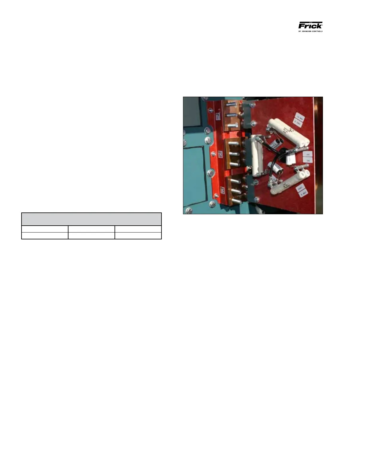
The output power attachment lugs are labeled “T1”, “T2”, and
“T3” are located on the inside right rear wall of the Vyper
™
cabinet (See Figure 19).
The power wiring emerges from the rectangular cutout on
the rear wall of the Vyper
™
cabinet (See Figure 14). These
connections are made in the factory and will be pretested
before shipment. For proper installation, connect an appropri-
ate conduit to the back cutout flange of the cabinet.
Figure 19 - Vyper
™
Output Power Terminal Connection Lugs