VYPER
™
VARIABLE SPEED DRIVE
OPERATION
100-210 IOM (JUL 09)
Page 53
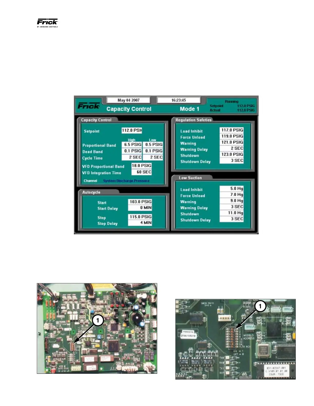
VSD LOGIC BOARD SETUP
The VSD logic board is equipped with a set of eight (8) DIP
switches (SW3), 1, that configure the RS-485 communication
between the logic board and Quantum
™
LX Panel as well as
the optional harmonic filter board. The logic board is mounted
inside the Vyper
™
cabinet. Refer to Figure 65.
Figure 65 - Vyper Logic Board
The first seven switches in SW3 configure MODBUS com-
munication address with the Quantum
™
LX Panel. To config-
ure the switches for proper communication, set switches 1
through 6 to the “OFF” position. Place switch 7 in the “ON”
position. The resulting MODBUS address is “0x40”. Refer
to Figure 65.
Switch 8 on SW3 allows harmonic filter communication.
Verify switch 8 is in the “ON” position to allow proper com-
munication. Refer to Figure 66.
Figure 66 - Logic Board SW3
With the actual pressure at 21psig the proportional com-
ponent would be 20%. The Proportional Component is
calculated as:
[(Actual Value – Setpoint) / PB] x (Maximum output – Mini-
mum Output).
[(21 – 20) / 4] x (100 – 20) = 20%
When this proportional component is added to the minimum
outpoint setpoint, the total output is 40% proportionally at
an actual value of 21 psig. It is the Integration Time setpoint
which will increase the output over time without an increase
in the actual value.
As long as the actual value (21 psig) does not change, the
Integration Time setpoint, in this case [30 sec], will increase
the output by the proportional component over every 30 sec-
onds to drive the actual value back to the Capacity Control
setpoint. If the actual value remains 21 psig, the Integration
Time Setpoint would increase the drive output to 100% over
1.5 minutes. (See Figure 64)
Figure 64 - Capacity Control Setpoints Screen