VYPER
™
VARIABLE SPEED DRIVE
INSTALLATION
100-210 IOM (JUL 09)
Page 26
VYPER
™
PREINSTALLATION SITE CHECKLIST
Before attempting to install a Vyper
™
Drive system, please perform a site inspection to assure that the following requirements
are met. (Where Applicable)
����������������������� Verify that the coolant (water or glycol) is available for the Vyper
™
heat exchanger connections. Hard-pipe the
coolant supply in accordance to all local and national piping codes. Sufficient coolant flow and temperature
levels must be available to the Vyper
™
VSD at installation. When hard-piping the coolant supply, take into
consideration that room is required in order to add coolant to the system.
����������������������� Verify that the compressor package temperature sensors are RFI suppression type (639A0151G01)
����������������������� Incoming power cables must enter through the panel supplied on the top of the left side of the unit. Power
cables must be in accordance with local and national electrical codes and current safety standards. See the
Power Wiring section in this manual for more details.
����������������������� Verify that the power cable lengths from the Vyper
™
to the compressor motor do not exceed 50 feet (15 meters)
and the location of the Vyper
™
is suitable for mounting.
����������������������� Verify that the motor is suitable for Inverter duty service: 20-100% speed. The motor must have thermal protec-
tion per NEC 2005. (RTD, Thermostat, Thermistor)
����������������������� Verify that the ambient temperature remains within the recommended operating range of 40° - 135°F (4° - 57°C).
If the drive is to operate below 40°F (4°C), provide enclosure ambient space heating.
����������������������� All wiring must be contained in metallic conduit. Use of PVC or other materials is not acceptable.
����������������������� Verify that control power (120 VAC), communications/analog wiring, and 460 VAC power are in separate metallic
conduits.
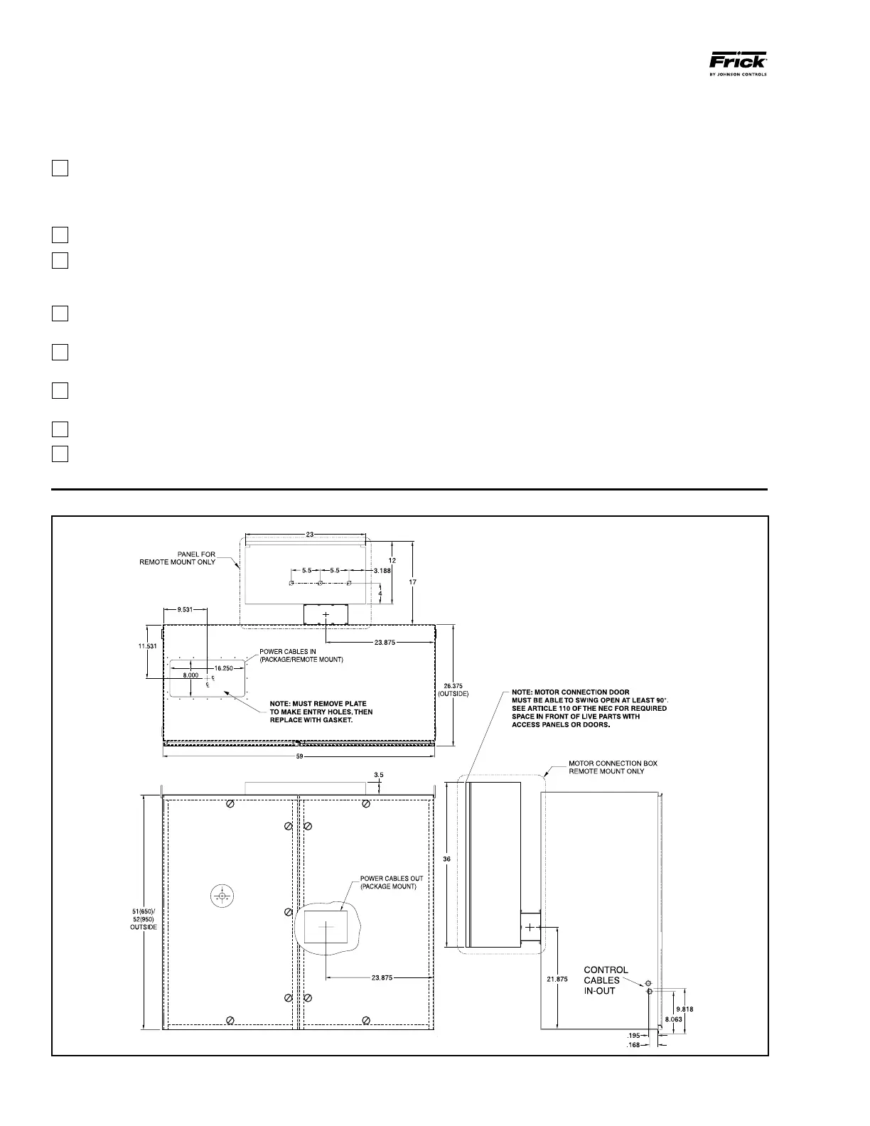
VYPER
™
POWER AND CONTROL ENTRY LOCATIONS
Figure 14 - Vyper
™
Cabinet Power and Control Entry Locations