VYPER
™
VARIABLE SPEED DRIVE
INSTALLATION
100-210 IOM (JUL 09)
Page 19
should be taken to ensure that the Vyper
™
and the associated
piping and wiring do not obstruct access to service areas.
VYPER
™
COOLING CONFIGURATION
The Frick Vyper
™
is internally cooled with a factory cali-
brated liquid cooling circuit that offers many advantages
over traditional air-cooled systems. The liquid circuit pro-
vides precisely controlled coolant temperatures to the heat
generating components and delivers coolant into locations
that air-over fan systems could not penetrate. The Vyper
™
liquid-cooling arrangement performs independently of fluctu-
ating ambient conditions. The NEMA 4 indoor-rated cabinet
seals the internal electronics and piping from corrosive
refrigerant vapors while providing superior cooling for the
internal electronic components. Efficient liquid cooling also
allows for smaller cabinet size and longer component life
than traditional air-cooled units. Plant condenser water or a
facility-supplied glycol loop subsequently removes the heat
in the coolant via the heat exchanger located at the back of
the Vyper
™
cabinet.
VYPER
™
COOLING LOOP
While the compressor is running, the Quantum
™
LX control
panel monitors the temperature of Vyper
™
drive coolant. With
this information, the Quantum
™
LX delivers a 4-20 mA signal
to the 3-way mixing valve, based on the setpoints of a PID
loop output from the Quantum
™
LX. This signal will maintain
the Vyper
™
coolant temperature at the control setpoint for
the PID loop. This setpoint will be set at 110°F at the factory.
There are also low and high temp alarms and shutdowns as-
sociated with the Vyper
™
coolant temperature reading. These
wil also be factory set for a Low Temp. alarm and shutdown
at 85°F and 80°F with a 90 second delay, when running. The
High Temp. Alarm and shutdown will be factory set at 125°F
and 130°F with a 30 second delay when running. If the Vyper
™
coolant temperature drops too low, condensation may occur,
damaging vital electronic components.
In addition to controlling the Vyper
™
cabinet cooling system,
the Quantum
™
LX panel also monitors the temperature of four
components in the Vyper
™
cabinet. If any of these tempera-
tures reaches a critical threshold, the Quantum
™
LX panel will
enter a Stop Load condition, preventing either the slide valve
position or motor speed from increasing. If the temperature
continues to rise, the Quantum
™
LX panel will next go to a
Force Unload condition. In this situation, the slide valve will
unload to lower the motor torque required, in an effort to drop
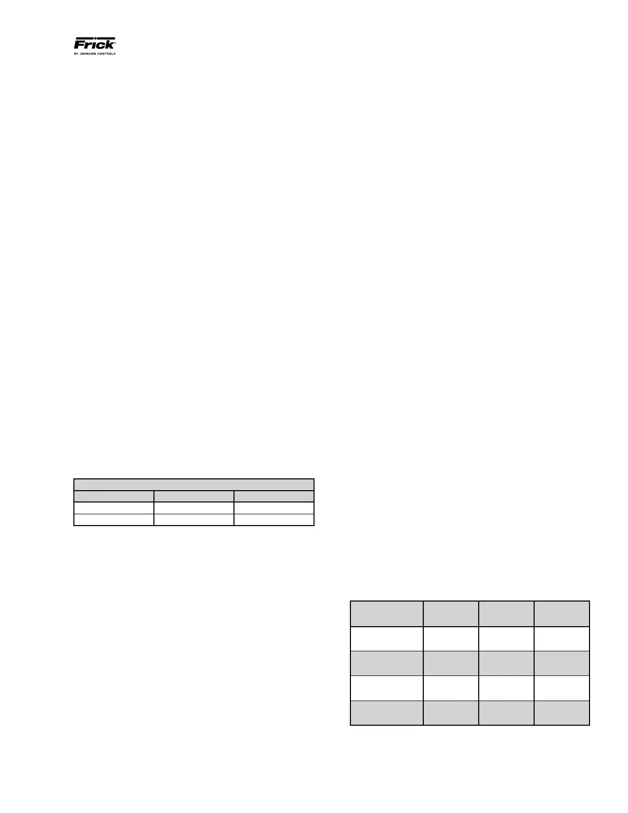
the temperature in the panel. Table 7 shows the Stop Load
and Force Unload temperatures as well as the temperatures
where the Vyper
™
cabinet will automatically shut down.
Location Stop Load
Force
Unload
Shutdown
Baseplate Temp
Inverter
160°F
(71°C)
165°F
(74°C)
170°F
(77°C)
Heat Sink Temp
155°F
(68°C)
160°F
(71°C)
158°F
(70°C)
Harmonic Filter
130°F
(54°C)
135°F
(57°C)
145°F
(63°C)
Baseplate Temp
160°F
(71°C)
165°F
(74°C)
175°F
(79°C)
Table 7 – Vyper
™
Cabinet Component Temperature Thresholds
REMOTE MOUNTED UNITS
For the remote mounting method, the Vyper
™
cabinet is
mounted on a steel stand specifically designed for the VSD.
The primary requirement for mounting the Vyper
™
is that the
foundation must be able to support the weight of the cabinet
and stand. In addition, the remote stand and Vyper
™
cabi-
net must be located so that no more than fifty (50) feet (15
meters) of motor wiring length is needed between the VSD
cabinet and the package motor.
The remote-mounted units have fastener holes located on
the bottom feet for floor anchors and on the rear stand legs
for wall anchoring of the stand.
Anchor bolts are recommended to firmly mount the unit to
the foundation. Anchoring the cabinet to a firm foundation
by proper leveling and employment of fastening bolts is the
best assurance for trouble-free installation.
Foundations must be in compliance with local building codes
and materials must be of industrial quality. All electrical
conduits must be metallic, no PVC or other materials are
permitted. The remote-mounted Vyper
™
configuration is
shown in Figure 7. Table 6 provides the dimensions of the
unit and stand. The mounting location of remote-mount units
must be able to support the weight of the Vyper
™
. Dimen-
sions of the package-mount cabinets are identical except for
the elimination of the stand. Coolant connections to the heat
exchanger are 1½ in. NPT.
ENVIRONMENT
The Vyper
™
is housed in a NEMA 4 indoor class enclosure.
The electronics are sealed against ambient conditions, how-
ever it is recommended that the end user employ good stan-
dard practices in regard to moisture exposure and extreme
temperature conditions. It is recommended that the Vyper
™
be operated within the ambient temperature range of 41°F
(5°C) and 135°F (57°C) with the dew point no higher than
90°F (32°C). Refer to Table 6 for temperature limits.
Recommended Ambient Temperature Limits
Unit Status Min Max
Storage -4°F (-20°C) 158°F (70°C)
Operating 41°F (5°C) 135°F (57°C)
Table 6 – Ambient Temperature Operating Limits.
The Vyper
™
can be used at altitudes up to 10,000 feet (3048
meters) without derating for units without the IEEE 519
Harmonic Filter. A Vyper
™
with the Harmonic Filter option
included can be operated up to 5,000 feet (1524 meters)
without derating. Remotely mounted units must have the
distance limited between the Vyper
™
and the compressor
motor to fifty (50) feet (15 meters) of wire or less. Problems
that may be encountered with wire lengths greater than fifty
feet are as follows:
• VSDpicksupinterferenceinthecontrolwiring,causing
the VSD to intermittently trip.
• Voltage drop becomes excessive, rising above the 5%
voltage drop limit.
• Peak voltage applied to the motor windings becomes
excessive and may cause premature motor failure.
• AdV/dt filter must be installed on remote-mounted units
with motor power lead lengths between 3 to 50 feet (1 to
15 meters).
Adequate service clearances, including door swing, must
be maintained around the Vyper
™
. During installation, care